SECTION 5
TROUBLESHOOTING
Aug 2002
p. 5-7
49836315
3.
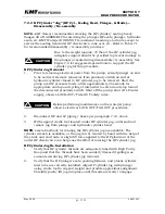
Start the intensifier pump, switch or adjust pressure to high pressure
(greater than 45,000 psi), then open HP nozzle valve.
4.
Without closing the HP hand valve, slowly turn hand valve handle in the
CLOSE direction, until a difference in stroke rate, i.e., a short stroke in one
direction, alternating with a long stroke in the opposite direction is
noticeable.
NOTE: Do not close the HP hand valve, but rather leave it at the metered position
giving the SHORT / LONG / SHORT / LONG stroking sequence.
5.
Observe LED lights on the hydraulic directional control valve (located above
the main hydraulic pump). Identify whether the left hand (LH) or right hand
(RH) LED light corresponds with the short stroke established in Step 4
above.
6.
If, e.g., the LH LED indicates short stroking in that direction, then either the
leak is in the RH INLET cutting water check valve or the LH OUTLET HP
water check valve.
7.
Conversely, if the RH LED indicates short stroking in the Right Hand HP
cylinder, either the LH INLET cutting water check valve or the RH OUTLET
HP water check valve is at fault.
8.
Combining the results of the dead head/ bleed down test described in
paragraph 5.5.2 above with the short stroke test described in steps 4 and 5
above, determine which HP cylinder (LH or RH) HP OUTLET check valve is at
fault.
NOTE: The bolted flange / metal-to-metal seal arrangement of the SLIV (Plus) sealing
head make the INLET check valves much more difficult to access for
maintenance than the HP OUTLET check valves. Therefore one should
generally rule out problems with the OUTLET HP check valves prior to
disassembling the INLET check valves.
______________________
Note 1: An alternative approach is to switch the HI/LO hydraulic pressure control
switch to LO pressure, which should slow the stroke rate enough to hear a
difference in plunger motion between HP cylinders. Study the LED’s on the
HP cylinders to decide in which direction the hydraulic piston is moving
rapidly, then decide which pair of INLET and OUTLET check valves are
suspect.
If equipped with proportional control, manually reduce pressure to 15,000-
25,000 psi to achieve an effect similar to operation in “LO” (low pressure
mode) discussed above.
Содержание STREAMLINE SL-IV PLUS
Страница 44: ...SECTION 6 LOW PRESSURE WATER May 2003 6 4 05148390 Figure 6 2 LP Cutting Water Supply Circuit ...
Страница 78: ...SECTION 7 HIGH PRESSURE WATER May 2003 p 7 30 49831951 ...
Страница 82: ...SECTION 8 ELECTRICAL SYSTEM Aug 2002 p 8 4 49836323 ...
Страница 111: ...SECTION 12 PARTS LISTS July 2003 page 12 5 49836349 ...
Страница 113: ...SECTION 12 PARTS LISTS July 2003 page 12 7 49836349 ...
Страница 115: ...SECTION 12 PARTS LISTS July 2003 page 12 9 49836349 ...
Страница 117: ...SECTION 12 PARTS LISTS July 2003 page 12 11 49836349 ...
Страница 119: ...SECTION 12 PARTS LISTS July 2003 page 12 13 49836349 ...
Страница 121: ...SECTION 12 PARTS LISTS July 2003 page 12 15 49836349 ...
Страница 123: ...SECTION 12 PARTS LISTS July 2003 page 12 17 49836349 ...
Страница 125: ...SECTION 12 PARTS LISTS July 2003 page 12 19 49836349 ...
Страница 127: ...SECTION 12 PARTS LISTS July 2003 page 12 21 49836349 ...
Страница 129: ...SECTION 12 PARTS LISTS July 2003 page 12 23 49836349 ...
Страница 131: ...SECTION 12 PARTS LISTS July 2003 page 12 25 49836349 ...
Страница 133: ...SECTION 12 PARTS LISTS July 2003 page 12 27 49836349 ...
Страница 135: ...SECTION 12 PARTS LISTS July 2003 page 12 29 49836349 ...
Страница 137: ...SECTION 12 PARTS LISTS July 2003 page 12 31 49836349 ...
Страница 139: ...SECTION 12 PARTS LISTS July 2003 page 12 33 49836349 ...
Страница 141: ...SECTION 12 PARTS LISTS July 2003 page 12 35 49836349 ...
Страница 143: ...SECTION 12 PARTS LISTS July 2003 page 12 37 49836349 ...
Страница 145: ...SECTION 12 PARTS LISTS July 2003 page 12 39 49836349 ...
Страница 146: ......
Страница 147: ......


