


SECTION 5
TROUBLESHOOTING
Aug 2002
p. 5-6
49836315
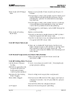
*I/O relay failure
Check if PLC output is shifting the I/O output relays
and allowing power to go to the coils on the
directional valve.
Directional valve coil
failure
Check coils on the directional valve with a volt meter to
verify good or bad
*PLC failure
If there are inputs from the proximity switches but no
outputs, contact IR service for a logic review and
verification of PLC failure.
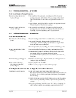
5.5 SPECIAL PROCEDURE—HP WATER CHECK VALVE TROUBLESHOOTING
5.5.1 HP Check Valve Troubleshooting
A leaking HP check valve is suspected if either HP cylinder or sealing head is
unusually hot. Compare temperatures of opposing sealing heads or HP
cylinders to decide location of hot spot. Note any heat in LP water ring or
hose fitting attached to LP water ring.
5.5.2 OUTLET HP Check Valve – Troubleshooting
1.
Start the pump. Set HP water to above 45,000 psi.
2.
Close HP water nozzle valve (deadhead the pump)
3.
Note pressure indication on HP water pressure gage.
4.
Turn the pump OFF, allowing HP water to remain trapped in HP piping and
HP attenuator.
5.
Wait approximately 60 seconds to see if HP water pressure “bleeds” down
6.
If gage pressure “bleeds” downward, then one of the HP OUTLET check
valves is the likely leak path.
NOTE: If the HP water nozzle valve is leaking, or if HP leaks exist elsewhere in the HP
water manifold, then the above test is less valid.
If the “bleed-down” test shows a leaking OUTLET HP water check valve, and if
one HP cylinder or sealing head is noticeably warmer than the other, then the
OUTLET check valve in that hot sealing head is probably leaking. If this
OUTLET HP check valve is not the problem, then continue to troubleshoot
the INLET cutting water check valves.
Note that cutting water entering the sealing head through the LP water ring is
normally cool. Any heat in the LP water near a sealing head is an indication
of HP water escaping from the HP cylinder back through the INLET cutting
water check valve.
5.5.3 INLET Cutting Water Check Valve – Troubleshooting (note 1)
1.
With the intensifer pump turned OFF, close a HP hand valve located in the
HP piping manifold between the pump and the cutting station.
2.
Open this HP hand valve approximately one turn.
Содержание STREAMLINE SL-IV PLUS
Страница 44: ...SECTION 6 LOW PRESSURE WATER May 2003 6 4 05148390 Figure 6 2 LP Cutting Water Supply Circuit ...
Страница 78: ...SECTION 7 HIGH PRESSURE WATER May 2003 p 7 30 49831951 ...
Страница 82: ...SECTION 8 ELECTRICAL SYSTEM Aug 2002 p 8 4 49836323 ...
Страница 111: ...SECTION 12 PARTS LISTS July 2003 page 12 5 49836349 ...
Страница 113: ...SECTION 12 PARTS LISTS July 2003 page 12 7 49836349 ...
Страница 115: ...SECTION 12 PARTS LISTS July 2003 page 12 9 49836349 ...
Страница 117: ...SECTION 12 PARTS LISTS July 2003 page 12 11 49836349 ...
Страница 119: ...SECTION 12 PARTS LISTS July 2003 page 12 13 49836349 ...
Страница 121: ...SECTION 12 PARTS LISTS July 2003 page 12 15 49836349 ...
Страница 123: ...SECTION 12 PARTS LISTS July 2003 page 12 17 49836349 ...
Страница 125: ...SECTION 12 PARTS LISTS July 2003 page 12 19 49836349 ...
Страница 127: ...SECTION 12 PARTS LISTS July 2003 page 12 21 49836349 ...
Страница 129: ...SECTION 12 PARTS LISTS July 2003 page 12 23 49836349 ...
Страница 131: ...SECTION 12 PARTS LISTS July 2003 page 12 25 49836349 ...
Страница 133: ...SECTION 12 PARTS LISTS July 2003 page 12 27 49836349 ...
Страница 135: ...SECTION 12 PARTS LISTS July 2003 page 12 29 49836349 ...
Страница 137: ...SECTION 12 PARTS LISTS July 2003 page 12 31 49836349 ...
Страница 139: ...SECTION 12 PARTS LISTS July 2003 page 12 33 49836349 ...
Страница 141: ...SECTION 12 PARTS LISTS July 2003 page 12 35 49836349 ...
Страница 143: ...SECTION 12 PARTS LISTS July 2003 page 12 37 49836349 ...
Страница 145: ...SECTION 12 PARTS LISTS July 2003 page 12 39 49836349 ...
Страница 146: ......
Страница 147: ......