KITCHENAID
Stand Mixer Service Manual LIT4177310-C 2005 KitchenAid
F.
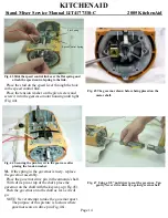
On international export models shown (Fig. 74),
a plastic head lock foot has been riveted to the
pedestal to permit the locking of the motor housing in
the “inclined” position.
The lock lever on these models is spring loaded and
the locking action is obtained by removing tension
from the lever after the motor housing has been put in
the “inclined” position (Fig. 74).
Fig. 74 A plastic headlock has been riveted to the pedestal
of international export models. An international model is
shown locked in the “inclined” position. This is obtained by
the action of the spring loaded lock lever used on these
models.
The small circuit board shown (Fig. 75) is an RF
filter used on international models that is held to the
bottom cover with a single round head screw.
Fig. 75 International model bottom cover with R F filter and
spring loaded lock lever.
SECTION 6
ADJUSTING THE CONTROL UNIT
NOTE:
When replacing a control plate, a cloth,
(Fig. 76), hooked over the control plate spring,
will keep the spring accessible, not allowing it to
“snap” between the upper and lower gear case and
become “lost.”
Fig. 76 Hold the control plate spring with a cloth to retain
access for reassembly.
A.
After installing new parts in the control unit,
the control plate must be adjusted so that all speeds
will be the same as they were when the mixer was
new.
B.
Make sure that all of the wire leads are properly
connected and that they are locked in position
properly.
Plug the cord into a receptacle having the proper
voltage.
C.
To adjust the speeds, move the switch lever to
stir.
This may or may not start the motor.
If motor did not start, turn out the two adjusting
screws evenly and stop when planetary turns about
60 revolutions per minute.
To test the speed, hold a finger of the right hand at
the planetary.
Let the beater shaft hit the finger (Fig. 77).
Count the number of times the finger is touched in
15 seconds.
Adjust the two screws until the shaft touches the
finger about 15 times in 15 seconds.
D.
When proper speed has been set, lock the two
lock nuts using a 11/32” wrench (Fig. 78) and
check the speed again.
Page 22
Control plate spring
Plastic headlock


