background image

2-3

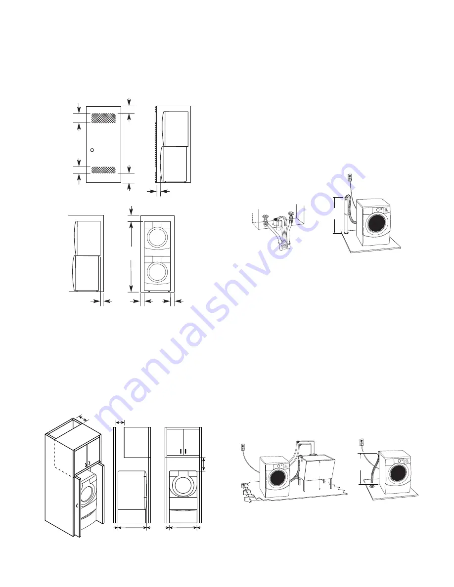
Recessed Or Closet Installation—
With Stacked Washer & Dryer

The  dimensions  shown  are  for  the  recom-
mended spacing.


* Min. top and bottom  air openings for closet door.


** External exhaust elbow requires additional space.

*** Wall, door and floor molding may require

additional spacing.

48 in.

2

 *

(310 cm


)

3" (7.6 cm)

6" (15.2 cm) 

76" 

(193 cm) 

27" 

(68.6 cm) 

3" (7.6 cm) 

1" (2.5 cm)

5-1/2"**

(14 cm)

1"*** 

(2.5 cm)

1"*** 

(2.5 cm)

24 in.

2

 *

(155 cm


)

Cabinet Installation

The  dimensions  shown  are  for  the  recom-
mended spacing. For cabinet installation with
a  door,  the  minimum  ventilation  openings  in
the top are required.

7" (17.8 cm)

9"
(22.9 cm)

7" (17.8 cm)

4"

(10.2 cm)

31-1/2"

(80.0 cm)

27"

(68.6 cm)

1"

(2.5 cm)

1"

(2.5 cm)

1"

(2.5 cm)

30" min.

(76.2 cm)

1

2

30" min.

(76.2 cm)

28" min.

(71 cm)

1

2

DRAIN SYSTEM

The washer can be installed using the standpipe
drain  system  (floor  or  wall),  the  laundry  tub
drain system, or the floor drain system. Select
the  drain  hose  installation  method  you  need
(see “Alternate Parts”).

Standpipe Drain System—
Wall Or Floor (View 1 & 2)

The standpipe drain requires a minimum diam-
eter  standpipe  of  2

  (5  cm).  The  minimum

carry-away capacity can be no less than 17 gal
(64 L) per minute.

The top of the standpipe must be at least 30

(76.2 cm) high and no higher than 96

″ 

(2.4 m)

from the bottom of the washer.

Laundry Tub Drain System (View 1)

The  laundry  tub  needs  a  minimum  20  gal.
(76 L) capacity. The top of the laundry tub must
be at least 30

 (76.2 cm) above the floor.

Floor Drain System (View 2)

The floor drain system requires a siphon break
that may be purchased separately (see “Alter-
nate Parts ”).

The siphon break must be a minimum of 28

(71 cm) from the bottom of the washer. Addi-
tional hoses might be needed.

Содержание KHWS01PMT / WH

Страница 1: ...TECHNICAL EDUCATION JOB AID 4317352 KAL 4 FRONT LOADING AUTOMATIC WASHER MODEL KHWS01PMT WH ...

Страница 2: ...vided with the washer The Wiring Diagram used in this Job Aid is typical and should be used for training purposes only Always use the Wiring Diagram supplied with the product when servicing the unit GOALS AND OBJECTIVES The goal of this Job Aid is to provide detailed information that will enable the service technician to properly diagnose malfunctions and repair the KitchenAid Ensemble Front Loadi...

Страница 3: ...CCESS 4 1 Component Locations 4 1 Removing The Console And The Touchpad LED Assembly 4 2 Removing The Door Lock Switch Assembly And The Front Panel Bellows 4 4 Removing The Flowmeter 4 7 Removing The Detergent Dispenser Motor Assembly 4 8 Removing The Inlet Valves 4 10 Removing The Central Control Unit 4 11 Removing The Interference Filter 4 12 Removing The Pressure Switch 4 13 Removing The Motor ...

Страница 4: ...olenoids 5 2 Door Lock Switch Assembly 5 3 Drain Pump Motor 5 4 Interference Filter 5 4 Heating Element Temperature Sensor 5 5 Heating Element Relay 5 5 Drive Motor 5 6 Interlock Switch 5 6 DIAGNOSTICS TROUBLESHOOTING 6 1 WIRING DIAGRAM 7 1 TECH TIPS 8 1 Manual Door Latch 8 1 Door Plunger 8 1 Page ...

Страница 5: ... SERIAL NUMBER PEDESTAL MODEL NUMBER L A B 27 0 0 P MT 0 PRODUCT GROUP L Domestic Laundry PRODUCT IDENTIFICATION A Laundry Accessory FEATURE CODE B Pedestal Base PRODUCT WIDTH FILLER FILLER YEAR OF INTRODUCTION COLOR CODE MT Meteorite Q White ENGINEERING CHANGE SERIAL NUMBER CS P 42 09793 DIVISION RESPONSIBILITY CS Schorndorf Germany YEAR OF PRODUCTION P 2003 WEEK OF PRODUCTION 42 42ND WEEK PRODUC...

Страница 6: ...1 2 MODEL SERIAL NUMBER LABEL AND TECH SHEET LOCATIONS The Model Serial Number label and Tech Sheet locations are shown below Model Serial Number Label Location Tech Sheet Location Behind Toe Panel ...

Страница 7: ... used with any other product than those listed in the installation instructions the warranty is null and void PEDESTAL WARRANTY Model Number Color Electrical Requirements Heating Power Max Current Rated Current Voltage Frequency Gallons Normal Cycle Capacity Volume Max Spin Speed Dimensions Height Height Feet Extended Width Depth Weight Installation Options Programs Program Selector Temperature Se...

Страница 8: ...ill not pay for 1 Service calls to correct the installation of your washer to instruct you how to use your washer or to replace house fuses or correct house wiring or plumbing 2 Repairs when your washer is used in other than normal single family household use 3 Damage resulting from accident alteration misuse abuse fire flood acts of God improper installation in stallation not in accordance with l...

Страница 9: ...ndard 20 gal 76 L 30 76 2 cm tall drain tub or utility sink and sump pump available from local plumbing supplier Floor drain Siphon break 285834 additional drain hose 8318155 and connector kit 285835 Drain hose too short Drain hose extension kit 285863 Water faucets beyond reach of fill hoses 2 longer water fill hoses 6 1 8 m 76314 10 3 0 m 350008 OPTIONAL STACK KIT To stack your washer and dryer ...

Страница 10: ...entire washer Installing the washer on carpeting is not recommended Asturdyandsolidfloortosupportthewasher with a total weight water and load of 400 lbs 180 kg Do not operate your washer in temperatures below 32 F 0 C Some water can remain in the washer and can cause damage in low tem peratures Installation Clearances The location must be large enough to allow the washer door to be fully opened Ad...

Страница 11: ...DRAIN SYSTEM Thewashercanbeinstalledusingthestandpipe drain system floor or wall the laundry tub drain system or the floor drain system Select the drain hose installation method you need see Alternate Parts Standpipe Drain System Wall Or Floor View 1 2 The standpipe drain requires a minimum diam eter standpipe of 2 5 cm The minimum carry away capacity can be no less than 17 gal 64 L per minute The...

Страница 12: ...s properly grounded Do not have a fuse in the neutral or ground circuit For a grounded cord connected washer This washer must be grounded In the event of a malfunction or breakdown grounding will reduce the risk of electrical shock by providing a path of least resistance for elec tric current This washer is equipped with a cord having an equipment grounding con ductor and a grounding plug The plug...

Страница 13: ...nd close the hose with the at tached cap REMOVE TRANSPORT SYSTEM 4 Close the bolt holes with the four transport bolt hole plugs CONNECT THE INLET HOSES Connect the inlet hoses to the water fau cets Make sure the washer basket is empty 1 Using a pair of pliers check the tightness of the hose couplings that are attached to the washer NOTE Do not overtighten the couplings or damage to the coupling ca...

Страница 14: ...her to its final location 4 Confirm the levelness of the washer COMPLETE THE INSTALLATION 1 Checktheelectricalrequirements Besure that you have the correct electrical supply and the recommended grounding method see Electrical Requirements 2 Check to be sure all parts are now in stalled If there is an extra part go back through the steps to see which step was skipped 3 Checktobesureyouhaveallofyour...

Страница 15: ...hoses at the faucets to relieve the water pressure 4 Remove the HOT and COLD fill hoses from the back of the washer Drain water in the hoses into a bucket 5 Squeeze the ears of the drain hose clamp with pliers to open and slide the clamp down the hose Disconnect the drain hose from the washer and drain any water in the hose into a bucket 6 Pull the washer away from the wall so it can be tipped on ...

Страница 16: ... the front of the washer and install the two remaining hex head sheet metal screws Do not tighten completely Align the sides of the pedestal so that they are even with the sides of the washer Reach inside the pedestal drawer open ing and securely tighten all four pedestal screws Washer Bottom Install Screws 6 Tip the washer and pedestal assembly back to an upright position and remove protective ca...

Страница 17: ... tighten the locknuts on all four feet against the pedes tal 11 Pull both drawer slides out and reas semble the drawer to the drawer slides with the two 2 phillips screws you re moved earlier NOTE Use of the two 2 dividers is optional 12 Close the pedestal drawer locknut ...

Страница 18: ...2 10 NOTES ...

Страница 19: ...the wash tub To improve cleaning of heavily soiled clothing and to provide a sanitizing feature the water tem perature can be increased through the use of a heating element located in the bottom of the tub FLOWMETER Water flow or the quantity of water introduced throughout any cycle is monitored by a flow meter and Central Control Unit When the flowmeter registers a maximum of 10 5 gal 40 L and th...

Страница 20: ... to accommodate either liquid or pow dered detergents The drawer release lever can be installed in the stack position to accommodate stacking a matching dryer on top of the washer The water enters the wash tub through the main inlet tube AIR VENT SYSTEM As a safety feature the washer is designed to allow fresh air to circulate through the tub An inlet vent at the rear of the washer brings air into...

Страница 21: ...ater introduced into the wash tub during the wash cycle Thepressureswitchalsosensesthesuds level in the wash tub If excessive sudsing occurs the washer starts an automatic suds routine The display will show the word Sud The automatic suds routine adds additional rinse and drain operations until the suds level is reduced If an overfill condition is detected by the pres sure switch the CCU will turn...

Страница 22: ...lay The CCU monitors the pressure switch flowmeter temperaturesensoranddoor lock switches TheCCUsendsthecustomerselectioninputto the Motor Control Unit for proper motor opera tion MOTOR CONTROL UNIT MCU The Motor Control Unit is located inside a plastic control box located in the lower front corner of the washer cabinet The control box is shown with the access door open The MCU operates the drive ...

Страница 23: ...nsures that no water or deter gent is wasted SUSPENSION SYSTEM The wash tub is held in position with four shock absorbers attached to the bottom four corners of the tub assembly In addition the wash tub is suspended from the top frame of the washer with two springs attached to the sides of the unit Stability for this suspension system is provided by three concrete counter weights Two are located a...

Страница 24: ...g element relay is located in the lower right hand side of the washer cabi net The CCU operates a solenoid to close the main relay contacts providing 120 VAC to the heating element The assembly contains a solenoid operated latching mechanism that will electrically lock the door during a wash cycle HEATING ELEMENT TEMPERATURE SENSOR Aheatingelementisusedtoincreasethewater temperature during certain...

Страница 25: ...odes Status Indicators Control On Wash Cycle Selector Hold To Start Display Off Pause Soil Level Change Any Time CUSTOMER INTERFACE CYCLE SELECTION Soil Level Changes the length of the wash cycle will add time to a normal wash cycle will shorten a normal wash cycle Hold To Start Initiates a wash cycle Press and hold the START button for one second OFF Pause Pressing this button will allow changing...

Страница 26: ...mum temperature Normal Casual Washes normally soiled cot tons and linens This cycle combines medium speed tumbling and high speed spin Rapid Wash Washes small loads of lightly soiled garments that are needed in a hurry This cycle combines fast speed tumbling a shortened wash time and extra high speed spin to shorten drying time Delicate Washes no iron fabrics in garments labeled Permanent Press or...

Страница 27: ...rains the washer or drains and spins a wash load The spin speed is preset to extra high If desired you can reduce the spin speed by selecting the speed you want from the SPIN SPEED modifier NOTE Loads of synthetics delicate fabrics handwashables and woolens should be drained with no spin or low spin speed to avoid fabric stress Cycle Soil Level Cycle Time Water Temp Spin Speed Sanitary Normal 1 55...

Страница 28: ...be added to the basket and the laundry will be equally distrib uted by a short tumbling phase Laundry will thenbesoakedinphaseswithoutbasketmove ment After soaking the washer drains without spinning Add detergent to both the Prewash and Main Washcompartmentsofthedispenserdrawer Use powdered detergent for the main wash cycle because liquid detergent will seep into the washer during Auto Soak For cy...

Страница 29: ...leave the loads dryer than cold rinses Warm rinses increase wrinkling In cold climates a warm rinse makes the load more comfortable to handle Cold rinses save en ergy MODIFIERS MODIFIERS To change cycle time select SOIL LEVEL button AutomaticTemperatureControl ATC Elec tronically senses and maintains a uniform wa ter temperature ATC regulates incoming hot and cold water ATC is automatically turned...

Страница 30: ...3 12 NOTES ...

Страница 31: ... shown below COMPONENT ACCESS Pressure Switch Central Control Unit Interference Filter Inlet Valves Flowmeter Detergent Dispenser Motor Assembly Tub Assembly Basket Drive Motor Motor Controller Drain Pump Heating Element Relay Front Interlock Switch Rear Interlock Switch Heating Element Temperature Sensor Airtrap Door Lock Switches Door Switch Not Shown Console Touchpad LED Assembly ...

Страница 32: ...p cover of the washer 4 Pull back on the cover and release the tabs in the console from the slots in the cover then lift the cover off the unit 5 To remove the console a Lift the locking tab and disconnect the ribbon cable connector from the cen tral control unit b Remove the ribbon cable from the five clips c Pull the detergent dispenser drawer out as far as it will go then press down on the rele...

Страница 33: ...l Out Lift 6 To remove the touchpad LED assem bly a Use a small screwdriver and unsnap the three top locking tabs from the touchpad LED assembly b Starting from the right unsnap the four lower locking tabs from the touchpad LED assembly and lift the assembly from the console NOTE If the push buttons are attached to the assembly unsnap them from the old assembly and install them on the console at t...

Страница 34: ...er supply to the washer 3 Remove the top cover and the console see page 4 2 for the procedures 4 Remove the three T 20 hex head torx screws from the toe panel and remove the panel Toe Panel Screws 6 Starting at the bottom use a small screw driver and pry the retaining wire from around the front of the bellows NOTE There is a tension spring at the bottom of the wire that can be separated to remove ...

Страница 35: ... 7 To remove the door lock switch as sembly a Remove the bellows retaining wire re fer to steps 5 and 6 for the procedure b Pull the bellows out and remove the three T 20 torx screws and flat wash ers from the door lock switch assembly c Push the switch assembly out of the front panel and then slide the assem bly tabs from the connector holder d Disconnect the three wire connectors from the switch...

Страница 36: ...the bel lows retainer clamp screw counter clockwise until the clamp is loose enough to remove from around the bellows Dispenser Tube Bellows Retainer Clamp Screw i Remove the bellows retainer clamp j Remove the bellows from the front of the tub Remove Bellows Retainer Clamp Remove Bellows ...

Страница 37: ...sult in death or electrical shock WARNING 1 Unplug washer or disconnect power 2 Turn off the water supply to the washer Flowmeter 4 Loosen the two clamps and remove the two hoses from the ends of the flowmeter 5 Disconnect the wire connector from the flowmeter 3 Remove the top cover and the console see page 4 2 for the procedures Wire Connector Flowmeter ...

Страница 38: ...ver and the console see page 4 2 for the procedures 4 To remove the detergent dispenser motor a Unhook the spring from the end of the water distribution lever b Carefully pull the cam actuator and the water distribution lever off the motor shaft then pull the water distribution lever off the lever connection pin Detergent Dispenser Motor Pull Off Shaft Disconnect Spring Remove From Pin Water Distr...

Страница 39: ... for the proce dure b Remove the detergent dispenser mo tor see step 4 Wire Clip c Use a small screwdriver and raise the locking arm so that it clears the tab Pull the inlet hose connector and rub ber o ring out of the detergent dis penser d Loosentheclampandpullthetubhose from the detergent dispenser e Remove the main inlet tube from the bellows f Remove the two screws from the de tergent dispens...

Страница 40: ...he water supply to the washer 3 Remove the top cover and the console see page 4 2 for the procedures Inlet Valves 4 Disconnect the four wire connectors from the inlet valve terminals 5 From behind the washer remove the inlet valve screw then slide the valves to the right and unhook them from the panel and remove them 6 Loosentheclampanddisconnectthehose from the water valves Disconnect The 4 Wires...

Страница 41: ...he top of the right column NOTE Each connector has a locking arm or locking tabs that you must release to remove the connector from the unit 6 Pry up on the two end locking tabs with a small screwdriver and unhook the central control unit from the washer Central Control Unit Serial Comm Link Temp Sensor Inlet Valves Disp Sw Mtr Drain Pump Door Lock Solenoids Unlock Wire Clip Unlock Wire Clip Wire ...

Страница 42: ...e water supply to the washer 3 Remove the top cover and the console see page 4 2 for the procedures Interference Filter 4 Disconnect the three connectors from the interference filter terminals NOTE The green 2 wire connector has a locking arm at the bottom that you must press to re lease the connector 5 RemovethetwoT 20hex headtorxscrews from the interference filter and remove the filter from the ...

Страница 43: ...ee page 4 2 for the procedures 4 Pull the pressure hose off the pressure switch inlet 5 Press on the two locking arms at the bottom of the wire connector and pull the connector off the pressure switch termi nals Pressure Switch Wire Connector Pressure Hose 6 Pry the standoff on the wire channel out of its chassis mounting hole 7 Turn the pressure switch 90 counter clockwise so that the square lock...

Страница 44: ...ct the four wire connectors from themotorcontroller NOTE Eachconnec tor has a locking arm or locking tabs that you must release to remove the connector from the unit 6 Cutthewiretieandpullthecuttieoutofthe slot in the standoff NOTE Be careful not to cut any of the wires in the tie 7 Lift the locking tab on the motor controller housing and slide the housing tabs for ward as far as they will go 8 Li...

Страница 45: ...4 15 REASSEMBLY NOTE After reinstalling the motorcontrollerhousing slideawiretiethrough the slot in the standoff and secure the wires to the standoff Wire Standoff ...

Страница 46: ...onnect the sensor connector b Pull the sensor out of the heating ele ment bracket hole Element Wires Ground Wire Electrical Shock Hazard Disconnect power before servicing Replace all parts and panels before operating Failure to do so can result in death or electrical shock WARNING 6 To remove the heating element a Remove the temperature sensor see step 5 b Disconnect the element wires and the gree...

Страница 47: ...the water supply to the washer 3 Remove the three T 20 hex head torx screws from the toe panel and remove the panel Heating Element Relay 4 Rotate the element relay holder so you can access the relay board 5 Unhook the wires from the holder then lift the relay and unhook it from the slots in the back of the holder 6 Pressthelockingarmsanddisconnectthe wire connectors from the relay Lift The Relay ...

Страница 48: ...20 hex head torx screws from the toe panel and remove the panel Drain Pump Assembly 4 Raise the drain pump wiring cover and disconnect the wire connector 5 Loosen the clamps and disconnect the drain and tub hoses from the drain pump 6 Remove the T 20 torx screw from the drain pump 7 Slide the drain pump forward in its mount ing slots and lift it out of the washer Do not remove the rubber washers f...

Страница 49: ...ly to the washer 3 Pull the washer away from the wall so that you can access the rear panel 4 Remove the twelve T 20 hex head torx screws from the rear panel and remove the panel from the washer Rear Panel Screw 1 of 12 5 Pull the pressure tube off the airtrap fitting 6 Remove the T 10 torx screws from the airtrap 7 Press the locking arm to unlock the airtrap and pull it back and off the tub NOTE ...

Страница 50: ...nd panels before operating Failure to do so can result in death or electrical shock WARNING 1 Unplug washer or disconnect power 2 Turn off the water supply to the washer 3 Depending on the interlock switch you are servicing remove the front panel see pages 4 4 and 4 5 for the procedure or the rear panel see page 4 19 for the procedure 4 Press in on the locking tab Slide the switch holder down in t...

Страница 51: ...4 21 6 Push out on the locking tabs of the switch holder rotate the switch up and remove it from the holder Locking Tabs Rotate Switch Up Switch Holder ...

Страница 52: ...nd remove the brace Electrical Shock Hazard Disconnect power before servicing Replace all parts and panels before operating Failure to do so can result in death or electrical shock WARNING Drive Motor Bottom Brace 6 Remove the drive belt from the end of the drive motor shaft and then remove the belt from the drive pulley 7 Disconnect the green ground wire from the drive motor frame 8 Removethe1 2 ...

Страница 53: ...s in the tie 11 Press the two locking arms down and disconnect the power connector from the motor 12 Disconnect the two green ground wires from the motor terminals 2 Ground Wires Wire Tie Power Connector 9 Pull the drive motor toward you and re move the pivot studs from the tub holes then turn the motor around so that you can access the motor wires Pivot Stud ...

Страница 54: ...emove the airtrap from the washer see page 4 19 for the procedure 7 Remove the drive motor and belt see page 4 22 for the procedure Electrical Shock Hazard Disconnect power before servicing Replace all parts and panels before operating Failure to do so can result in death or electrical shock WARNING 9 Loosen the clamp and pull the end of the air inlet hose from the tub Top Brace 8 Remove the T 20 ...

Страница 55: ... and pull the end of the drain hose from the tub 11 Remove the three T 20 torx screws from the drive motor shield and remove the shield from the bottom of the tub Drain Hose Motor Shield Rear Counterweight b Twist the top section so the tabs align with the slots in the tub c Lowerthetopofthestrutdownthrough the slot and rotate the shock absorber against the floor of the cabinet Locking Tab Align T...

Страница 56: ... wire ties Wire Ties In Standoffs Top Front Brace IMPORTANT NOTE When you remove the bottom front counterweight in the following step be sure to support it with one hand while you remove the screws with the other hand otherwise the weight will fall and could cause an injury or damage the floor covering 17 Whilesupportingthebottomfrontcounter weight with one hand remove the three 1 2 hex head bolts...

Страница 57: ...d in the front slots of the cabinet as well as in the tub Do not use the back slots they are used with other models 21 Remove the 15 16 hex washer nut from the drive pulley and remove the pulley from the basket shaft Front Slot Front Slot Front Slots 22 Mark the edges of the 23 tub clamps with apencilsothatyoucanreinstalltheclamps in the same locations later 23 Useascrewdriverblade andpryoffthe23 ...

Страница 58: ...asket 26 Toreplacetheheaterelementwireholder remove the T 20 torx screw 27 To replace the tub gasket pry the gasket out of the slot and remove it NOTE The basket hub is molded into the rear half of the tub If it is worn and needs to be replaced you will need to replace the rear half of the tub Heating Element Wire Holder Tub Gasket Basket Hub ...

Страница 59: ...sion springs into the front holes of the tub and cabinet Front Slot Front Slot Front Slots 3 When reinstalling the bottom front coun terweight first tape the flat nut in place in the tub slot so it does not fall out Bottom Front Counterweight Flat Nut 4 When reinstalling the heating element in the tub make sure that it is held in place by thewireholder seethephotoinstep27on the previous page Heati...

Страница 60: ...4 30 NOTES ...

Страница 61: ...disconnected Unless stated otherwise make all resis tance checks by disconnecting the compo nent connector at the Central Control Unit CCU WARNING Electrical Shock Hazard Disconnect power before servicing Replace all parts and panels before operating Failure to do so can result in death or electrical shock PRESSURE SWITCH Refer to page 4 13 for the procedure for servic ing the pressure switch 1 Un...

Страница 62: ...nser switch at pins 5 and 6 0 Ω Refer to page 4 10 for the procedure for servic ing the inlet valves 1 Unplug washer or disconnect power 2 Disconnect the inlet valve solenoid con nector from the CCU 3 Set the ohmmeter to the R x 100 scale 4 Touch the ohmmeter test leads to the indicated wire connector terminals The meter should indicate between 750 and 850 Ω INLET VALVE SOLENOIDS WARNING Electrica...

Страница 63: ...ches a Turn the washer on and select a cycle b Press START and you should hear the door lock solenoids engage c Unplug the washer from the wall out let d Disconnect the door lock main switch connector from the CCU e Touch the ohmmeter test leads to the indicated connector terminals The meter should indicate as follows Main switch 1 at pins 4 and 5 0 Ω Main switch 2 at pins 6 and 7 0 Ω 45 67 2 1 1 ...

Страница 64: ...nce filter terminals 3 Set the ohmmeter to the R x 10K scale 4 Touch the ohmmeter test leads to the interference filter connector pins The meter should indicate approximately 450K Ω DRAIN PUMP MOTOR Refer to page 4 18 for the procedure for servic ing the drain pump assembly 1 Unplug washer or disconnect power 2 Disconnect the drain pump motor connec tor from the CCU 3 Set the ohmmeter to the R x 1...

Страница 65: ...eter should indicate as shown in the following chart Heating Element Temperature Sensor Connector HEATING ELEMENT RELAY Refer to page 4 17 for the procedure for servic ing the heating element relay 1 Unplug washer or disconnect power 2 Disconnecttheheatingelementrelaycon nector from the CCU 3 Set the ohmmeter to the R x 1 scale 4 Touch the ohmmeter test leads to the two relay connector pins The me...

Страница 66: ...er test leads to the two interlock switch terminals The meter should indicate an open circuit with the actuator in and a closed circuit 0 Ω with the actuator out DRIVE MOTOR Refer to page 4 22 for the procedure for servic ing the drive motor 1 Unplug washer or disconnect power 2 Disconnect the wire connector from the drive motor terminals 3 Set the ohmmeter to the R x 1 scale 4 Touch the ohmmeter ...

Страница 67: ...liance Avoid touching electronic parts or terminal contacts handle electronic control board by edges only When repackaging failed electronic con trolboardinanti staticbag observeabove instructions DIAGNOSTIC GUIDE Before servicing check the following Make sure there is power at the wall outlet Hasahouseholdfuseblownorcircuitbreaker tripped Time delay fuse Are both hot and cold water faucets open a...

Страница 68: ...on all the way Check for plugged or kinked inlet hoses or plugged screens in the inlet valves Verify inlet valve operation If there is water in the unit Verify drain pump operation Verify that the pressure switch hose is in good condition and properly connected to tub and pressure switch 1 Verify there is not a siphon problem 2 Unplug washer or disconnect power 3 Verify wire harness connections to...

Страница 69: ...t of range the F 05 error code will be displayed Possible Causes Procedure 1 Unplug washer or disconnect power 2 Check the water temperature sensor Refer to the Water Temperature Sensor section Check connections to the water temperature sensor 3 Check resistance of heating element if present on this model abnormal infinity F 05 F 05 F 02 F 02 LONG DRAIN If the drain time exceeds eight minutes the ...

Страница 70: ... PAUSE CANCEL is pressed twice and the display is cleared Turn off hot and cold water faucets and unplug the unit before servicing Possible Causes Procedure 1 Check the drain hose and make sure it is not plugged or kinked 2 Unplug washer or disconnect power 3 Check wire harness connections to the drain pump pressure switch and Central Control Unit CCU 4 Check clean drain pump filter of foreign obj...

Страница 71: ...n washer or reconnect power 5 Verify CCU operation by running a Diagnostic test or any cycle 6 Check the MCU by looking for operations of the drive motor 7 Check the drive motor for powered rotations 8 Check that the serial harness at the MCU is not mounted upside down The wires should be to the left when facing the MCU connectors F 13 F 13 DISPENSER CIRCUIT ERROR If the dispenser motor is not abl...

Страница 72: ... selecting different cycles and changing the modifiers and options available to confirm the touchpad LED is responding 2 Unplug washer or disconnect power 3 Check wire harness connections to the touchpad LED assembly and Central Control Unit CCU F 21 F 21 F 22 F 22 DOOR UNLOCK ERROR A Door Unlock Error occurs if the door cannot be unlocked It will try to unlock the door six times before displaying...

Страница 73: ...nit through a Rinse Spin cycle Run a Normal cycle without adding any detergent This should clear the unit of the excess detergent 1 Check the drain hose and make sure it is not plugged or kinked 2 Unplug washer or disconnect power 3 Check wire harness connections to the drain pump pressure switch and Central Control Unit CCU 4 Check clean drain pump filter of foreign objects 5 Plug in washer or re...

Страница 74: ... on this model press RINSE HOLD two times Indication Actuators To Be Checked Control Action C 00 Drum rotates counterclockwise at maximum speed If max speed EXTRA HIGH drum speed 1000 rpm If max speed HIGH drum speed 800 rpm Door lock system Flowmeter Cold water inlet valve Dispenser motor Dispenser contact Hot water inlet valve Motor Motor Control MCU Heater if present on this model NTC Drain pum...

Страница 75: ...followingtable An abnormal condition is an open circuit Normal 6 Ω approximate Abnormal Infinity Results Pins 1 to 2 2 to 3 1 to 3 Temperature Results 32 F 0 C 35 9 kΩ 86 F 30 C 9 7 kΩ 104 F 40 C 6 6 kΩ 122 F 50 C 4 6 kΩ 140 F 60 C 3 2 kΩ 158 F 71 C 2 3 kΩ 203 F 96 C 1 kΩ Manually Unlocking The Door Lock System 1 Unplug washer or disconnect power 2 Remove the lower kick panel 3 Reach up along the ...

Страница 76: ...sembly wire harness from the CCU 3 Remove dispenser drawer 4 Remove left front screw that was covered by the dispenser drawer 5 Opendoor underthecenterofthetouchpad LED assembly there is a notch insert a flat blade screwdriver in notch to release the bottom of the touchpad LED assembly 6 Ontherighthandsidebehindthetouchpad LED assembly press tab to release right side of the touchpad LED assembly 7...

Страница 77: ... 5 Check the wire harness connections 6 Plug in washer or reconnect power 7 Check the touchpad LED assembly by selecting different cycles and changing the modifiers and options available to confirm the touchpad LED is responding 1 Check for a Fault Error Code on the display 2 Press PAUSE CANCEL button on the touchpad twice 3 Check the touchpad LED assembly by selecting different cycles and changin...

Страница 78: ...ng pressure switch 6 Check drain pump motor 7 Verify CCU operation by running a Diagnostic test or any cycle 8 Check under problem Will Not Dispense 1 Verify the unit is level 2 Check pump drain system This could indicate a failure to drain 3 Check operating pressure switch 4 Check pressure switch hose 5 Verify flow meter operation by blowing air though the part and measuring the resistance 6 Veri...

Страница 79: ...ns 3 Check drain pump 4 Check drain pump motor 5 Check that the drain hose and drain pump filter are clear of foreign objects 6 Plug in washer or reconnect power 7 Verify CCU operation by running a Diagnostic test or any cycle 1 Check that the inlet hoses are connected properly 2 Unplug washer or disconnect power 3 Check the water heater and wire harness connections to it 4 Check water temperature...

Страница 80: ...6 14 NOTES ...

Страница 81: ...7 1 WIRING DIAGRAM ...

Страница 82: ...7 2 NOTES ...

Страница 83: ...n the OUT position it prevents the door from latching 4 Located on the bottom of the door latch assembly is a teardrop shaped tab Gently pull the tab down approximately 1 4 or until a click is heard 5 The door may now be manually opened DOOR PLUNGER To activate the child lock feature insert a coin in the plunger slot and rotate it counterclock wise until the button pops out left photo To deactivat...

Страница 84: ...8 2 NOTES ...

Страница 85: ...RIZED SERVICER FOR LITERATURE ORDERS PHONE 1 800 851 4605 FOR TECHNICAL INFORMATION AND SERVICE POINTERS www servicematters com IN CANADA FOR PRODUCT SPECIFICATIONS AND WARRANTY INFORMATION CALL 1 800 461 5681 FOR TECHNICAL ASSISTANCE WHILE AT THE CUSTOMER S HOME CALL THE TECHNICAL ASSISTANCE LINE 1 800 488 4791 HAVE YOUR STORE NUMBER READY TO IDENTIFY YOU AS AN AUTHORIZED SERVICER FOR WHIRLPOOL P...

Страница 86: ......

Отзывы: