7
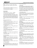
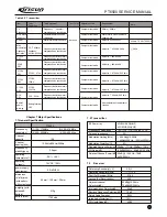
Table 3.8 CF1 LTWC450F Features
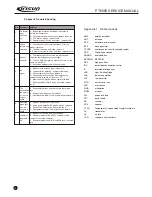
Chapter 4 Function Description and Parameter Setting
Major Functions
4.1.1 128 channels
The radio stores 128 channels and can allocate there channels in 8
different zones
Zone 0
cannot be programmed and includes
all channels
8 Zones
There are 8 zones numbered from
Except
Zone0
all other zones can be freely allocated with up to 16 channels
.
Zone0
includes all channels and cannot be programmed. Only
when the previous zone is allocated with at least 1 channel can the
following zone be allocated.
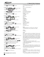
4.1.3 Channel scanning (this feature can be disabled by
programming software)
There are 16 scanning lists, each of which can be allocated with up
to 16 channels, which can be from the same or different channels.
In channel setting, you can select a scanning list for the channel. If
the channel is chosen by using the channel selection key, the
chosen scanning list for the channel can be started by the
programmable key set to
scanning
or Manu operation.
a.
Activate the scanning function by pressing the key set as the
Scan
function or Manu operation to scan the specified
scanning list.
When scanning, the radio will search signals of each channel till
signals are found, if the time delay between the disappearance of
signals and the resumption of scanning is set, if any signal is
received during the time delay, the radio will still stay in this channel.
Note: The current channel must be provided with a scanning list or it
cannot be activated. Scanning is available only when there're at
least 2 channels programmed in the scanning list and the scanning
is valid.
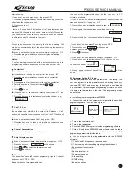
b.
Revert channel (the transmitting channel when scanning) during
the scanning set by the dealer has the following options:
In the Scan mode, the radio can be set as to return to a specified
channel when pressing the [PTT] key.
With this function, the radio can be customized so as to meet the
requirements of the user when using the scanning function.
Revert channel has the following types:
Fixed channel
,
Selected channel
,
SCurrent Channel
,
Priority
1+ Current Channel
,
Priority 2 + Current Channel
,
Priority
1
and
Priority channel 2
. In all cases, the user can manually
select one channel for transmitting. (This will resume the revert
channel to the selected channel)
Fixed channel:
The channel specified for programming.
Selected channel: The channel selected by the scanning selector
4.1
.
4.1.2
0
~
7
.
PT6500 SERVICE MANUAL
Specified Value
450kHz
6.0kHz or bigger
12.5kHz or smaller
2.0dB or smaller within f0
4kHz
6.0dB or smaller
47.0dB or bigger within f0
100kHz
1.5k
Item
Nominal center frequency
6dB bandwidth
50dB bandwidth
Pulse
Insertion loss
Guarantee attenuation
Terminal resistance
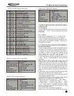
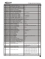
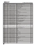
Table 3.5 Diode Function Description
Position
D1
D10
D11
D12
D13
D14
D15
D16
D17
D18
D19
D2
D21
D22
D23
D26
D27
D28
D28
D29
D3
D30
D31
D35
D36
D37
D39
D4
D40
D5
D6
D7
D9
Type
HVC131
MA2S111
HVC376
HVC376
HVC376
HVC376
HZU5ALL
MA2S111
HSC277
DAN222
DAN222
HVC376
HVC355B
MA742
HVC355B
LED green
HVC376B
LED red
HVC376B
HVC376B
HSC277
HVC376B
LED green
MA742
MA742
MA742
HVC131
HVC376
HVC376B
HVC376
HVC376
HSC277
1SV278
Function Description
Transmitter antenna switch diode
Loss of lock detection diode
Receiver's VCO oscillation variode
Receiver's VCO oscillation variode
Receiver's VCO oscillation variode
Receiver's VCO oscillation variode
APC output voltage limiting diode
VCO power filtering acceleration diode
VCO output switch
nd
Receiver's 2 IF filter band switch
nd
Receiver's 2 IF filter band switch
Remitter's VCO oscillation variode
Receiver's band pass filter oscillation variode
Noise demodulation
Receiver band pass filter oscillation variode
Receiving indication
Receiver band pass filter variode
Transmitting indication
Receiver band pass filter variode
Receiver band pass filter variode
VCO output switch
Receiver band pass filter variode
Receiving indication
VOX detection diode
MIC AGC detection diode
MIC AGC detection diode
Transmitter's antenna switch diode
Transmitter's VCO oscillation variode
Receiver's band pass filter variode
Transmitter's VCO oscillation variode
Transmitter's VCO oscillation variode
Antenna switch
Remitter's VCO modulation diode
Table 3.6: Features of XF1 Crystal Filter
Item
Nominal center frequency
Transmitting bandwidth
40dB Barrage bandwidth
Pulse
Insertion loss
Guarantee attenuation
Terminal resistance
Specified Value
51.65MHz
7.5kHz or bigger within 3dB
20.0kHz or smaller
1.0dB or smaller
3.0dB or smaller
80dB or bigger within fo-910kHz
330
Table 3.7 CF1 LTWC450H Features
Specified Value
450kHz
3.0kHz or bigger
9.5kHz or smaller
2.0dB or smaller within f0
4kHz
6.0dB or smaller
47.0dB or bigger within f0
100kHz
1.5k
Item
Nominal center frequency
6dB bandwidth
50dB bandwidth
Pulse
Insertion loss
Guarantee attenuation
Terminal resistance
Содержание PT6500
Страница 1: ...PROFESSIONAL TWO WAY RADIO PT6500 V071208 FM PORTABLE RADIO SERVICE MANOAL Welcome ...
Страница 33: ...PT6500 SERVICE MANUAL Figure 1 PT6500 Top Main Board Position Number Diagram 136 174MHz 32 ...
Страница 34: ...PT6500 SERVICE MANUAL Figure2 PT6500 Bottom Main Board Position Number Diagram 136 174MHz 33 ...
Страница 35: ...Figure 3 400 470MHz PT6500 Top Main Board Position Number Diagram 34 PT6500 SERVICE MANUAL ...
Страница 36: ...35 PT6500 SERVICE MANUAL Figure 4 400 470MHz PT6500 Bottom Main Board Position Number Diagram ...
Страница 37: ...Figure 5 PT6500 PTT Top Board Position Number Diagram 36 PT6500 SERVICE MANUAL ...
Страница 38: ...37 PT6500 SERVICE MANUAL Figure 6 PT6500 PTT BOTTOM Board Position Number Diagram ...


