


10
PT6500 SERVICE MANUAL
5
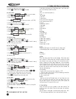
Set the Rx FRQ value with the keypad,
6. Press to delete, and press to confirm.
Set Tx FRQ
1
As shown: in CH 1 , press to enter select mode,
2. Press / , and Ch Edit is shown,
3. Press to select
P
4
P
1
P
4
P
2
P
3
Ch alias
CHANNEL 1
4. Press , is shown, enter the set of Tx FRQ,
5
Set the Tx FRQ value with the keypad,
6. Press to delete, and press to confirm.
Set Rx CTCSS/DCS
1
As shown: in CH 1 , press to enter select mode,
2. Press / , and Ch Edit is shown,
3. Press to select
4. Press , is shown, enter the set of Rx
CTCSS/DCS FRQ
5
Set the Rx FRQ value with the keypad,
6. Press to delete, and press to confirm.
7. Stands for the radix point, press
to convert among
CTCSS
DCS and reverse DCS.
Set Tx CTCSS/DCS
1
As shown: in CH 1 , press to enter select mode,
2. Press / , and Ch Edit is shown,
3. Press to select
4. Press , is shown, enter the set of Tx
CTCSS/DCS FRQ,
5. Set the Tx FRQ value with the keypad,
6. Press to delete, and press to confirm.
7. Stands for the radix point, press
to convert among
CTCSS
DCS and reverse DCS.
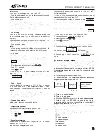
Set contact list
1
As shown: in CH 1 , press to enter select mode,
2. Press / , and Contact List is shown,
3. Press to select,
4. Select the address cable of the call to be made with / ,
5
Check the alias or address code by turning the knob,
6. Key in the address code of the person you are calling,
7. Press to transmit the current contact list.
Set status:
1
As shown: in CH 1 , press to enter select mode,
2. Press / , and Status is shown,
3. Press to select,
4.Select the needed status with / ,
5. Check the alias or address code of the status by turning the
knob,
6. Press to select the current status.
PROGRAMMABLE BUTTON FUNCTIONS
The dealer can program the 2 Side Buttons and 1 top Button with
one of the following auxiliary functions.
None
OFF (
do not set the functions
)
Scan
lone working
Contact list
Power selector
Show or hide the channel alias
Busy Channel Lockout (BCL)
T x F R Q
401.660000
P
3
P
4
P
1
Ch alias
CHANNEL 1
P
2
P
3
P
4
P
4
Rx CTCSS
401.660000
P
3
P
4
P
1
*
Ch alias
CHANNEL 1
P
2
P
3
P
4
P
4
Tx CTCSS
XXXX
P
3
P
4
P
1
*
P
2
P
3
P
4
P
4
P
4
P
2
P
3
P
2
P
3
P
4
P
4
P
4
P
2
P
3
Key lock
Squelch level selector
Companding
Scrambler
Battery power
Zone
Monitoring
Cancel Squelch
Emergency Alert
Back light
Rptr/Talkarnd
Express select channel 1
Express select channel 2
Call 1, 2, 3 or 4
Channel lock
Adjust display contrast
Notes:
Programmable key can be set as short press or long press.
The following functions can be programmed by the dealer:
None
Set of None
Scan
Press the button set as Scan to start scanning. When carrier wave
scan is enabled. While in scanning, the radio checks every channel
(any channel in any zone) and stops on the channel on which a
signal is detected until that signal disappears. If interval between
signal disappearing and continuing scanning has been preset, the
radio will remain on that channel. Only when there are two channels
added in the scan list and the scan function has been activated, the
radio can start scanning.
start scanning.
It can be set as: short press: scan, long press
OFF.
1. Press the programmable key once to start scanning (it should be
effective in the channel scan list).
2. Press once to quit.
Notes:
there are 8 zones from 0 (default zone) to 7; and there can be as
many as 128 channels in each zone. There are totally 16 scan lists;
you can select any scan list. Every scan list can scan any channels
in different zones (16 channels to the most).
Lone working
Press the button set as lone working to start lone working. This
mode is to ensure the safety of the user while using the transceiver
separately.
It can be set as: short press : personal working, long press
OFF.
1. Press the programmable key once to start personal working;
Содержание PT6500
Страница 1: ...PROFESSIONAL TWO WAY RADIO PT6500 V071208 FM PORTABLE RADIO SERVICE MANOAL Welcome ...
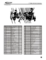
Страница 33: ...PT6500 SERVICE MANUAL Figure 1 PT6500 Top Main Board Position Number Diagram 136 174MHz 32 ...
Страница 34: ...PT6500 SERVICE MANUAL Figure2 PT6500 Bottom Main Board Position Number Diagram 136 174MHz 33 ...
Страница 35: ...Figure 3 400 470MHz PT6500 Top Main Board Position Number Diagram 34 PT6500 SERVICE MANUAL ...
Страница 36: ...35 PT6500 SERVICE MANUAL Figure 4 400 470MHz PT6500 Bottom Main Board Position Number Diagram ...
Страница 37: ...Figure 5 PT6500 PTT Top Board Position Number Diagram 36 PT6500 SERVICE MANUAL ...
Страница 38: ...37 PT6500 SERVICE MANUAL Figure 6 PT6500 PTT BOTTOM Board Position Number Diagram ...