16
PT6500 SERVICE MANUAL
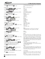
range of 0~255 range.
6.3.9 Receiver volume
(HP8920 set at the RX status, filter set
at 50Hz~15kHz)
A.
Max broadband receiver volume: input the RF signal with
adjusted frequency and the amplitude at -47dBm and the
modulation frequency deviation at 3kHz at the antenna port of the
radio. Under
the computer test mode, select
Max broadband receiver
volume
to enter and adjust the audio power at 1.8W within the
range of 0~64 range.
B.
Max narrowband receiver volume: input the RF signal with
adjusted frequency and the amplitude at -47dBm and the
modulation frequency deviation at 1.5 kHz at the antenna port of the
radio. Under the computer test mode, select
Max narrowband
receiver volume
to enter and adjust the audio power at 1.8W
within the range of 0~64 range..
Item
Setting
Locked
voltage
Test
Condition
Battery
7.5V
CH: RX High
Frequency
CH: RX Low
Frequency
CH: TX High
Frequency
CH:TX Low
Frequency
cap
Acity:
Test
Equipment
Digital
Multimeter
Test
Point
PD
Adjustm
ent
Part
C117
C52
Require
ment
4.2V
0.1V
>0.6V
4.2V
0.1V
>0.6V
Note
Adjust
ment
Watch
ing
Adjust
ment
Watch
ing
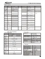
Table 6.3 Voltage Controlled Oscillator
Table 6.4 Receiver
Item
Band pass
filter
Audiopower
Sensitivity
Squelch
activation
Test Condition
Test frequency intermediate
frequency
Antenna port
input
RF OUT
-47dBm(1ìV)
MOD
1kHz
DEV
3.0kHz/
1.5kHz
Audio load
16Ù
CH: center frequency
CH:low frequency
CH:high frequency
RF OUT:
-119dBm(0.25ìV)
MOD: 1kHz
DEV: 3.0kHz/
1.5kHz
CH: RX center frequency
th
9
RF OUT:-117dBm
rd
3
RF OUT:-124dBm
Test Point
Before
mixing
Speaker
connector
Adjustment Part
Computer test
Computer test
Computer test
Computer test
Requirement
Smooth wave
(Turn the volume
knob clockwise)
audio power >1.5W
SINAD:
12dB or higher
After adjustment,
squelch activation
is normal
After adjustmen t
squelch activation
is normal
Note
No adjustment is
recommended
Inner speaker
power >
1.2W
Test Equipment
Frequency spectrum Analyzer /
comprehensive test Device
RF Signal
generator
Oscillator
Audio Voltmeter
DistortIon test
device
/Comprehensive
test
device
6.4 Debugging
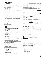
The above debugging refers to Table3, Table4, and Table 5.
Содержание PT6500
Страница 1: ...PROFESSIONAL TWO WAY RADIO PT6500 V071208 FM PORTABLE RADIO SERVICE MANOAL Welcome ...
Страница 33: ...PT6500 SERVICE MANUAL Figure 1 PT6500 Top Main Board Position Number Diagram 136 174MHz 32 ...
Страница 34: ...PT6500 SERVICE MANUAL Figure2 PT6500 Bottom Main Board Position Number Diagram 136 174MHz 33 ...
Страница 35: ...Figure 3 400 470MHz PT6500 Top Main Board Position Number Diagram 34 PT6500 SERVICE MANUAL ...
Страница 36: ...35 PT6500 SERVICE MANUAL Figure 4 400 470MHz PT6500 Bottom Main Board Position Number Diagram ...
Страница 37: ...Figure 5 PT6500 PTT Top Board Position Number Diagram 36 PT6500 SERVICE MANUAL ...
Страница 38: ...37 PT6500 SERVICE MANUAL Figure 6 PT6500 PTT BOTTOM Board Position Number Diagram ...

