PT6500 SERVICE MANUAL
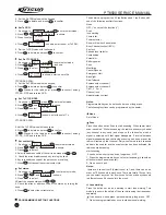
10) Monitor mode option;
11) Scan mode option;
12) Scan the reverting channel option;
13) Scan the priority channel selection;
14) Call list setting;
15) Customized tones;
For more details, please refer to the
Help
document of
KSP6500 software.
Note: 1. Turn off the radio before connection.
2. When the radio is being read data, the indicator lights orange and
it's prohibited to press the PTT button; when the radio is being
written data, the indicator lights orange.
3. Before the first time editing, you should read data form the radio
and backup the data.
4
If the radio cannot work normally after being written in with the
editing data, open the data backup and rewrite the backup into the
radio.
5
Model information is important radio data and is prohibited to
modify.
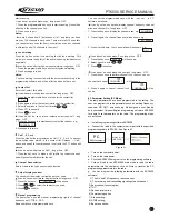
4.4 Computer Test Mode:
Connect the radio to the radio communication port with the
specified programming cable (KSPL-09). See Figure 4.1.
Warning: Before enter the computer test mode, connect a HF
load of 50Ù to the radio antenna connector or connect the
radio to a comprehensive test device.
Under the computer test mode, you can modify the following
parameters with KSP6500 programming
software:
1) Frequency stability
2) Transmitting H/I/L power;
3) Max audio frequency deviation;
4) DTMF frequency deviation;
5) MSK frequency deviation;
6) QT frequency deviation;
7) DQT balancing;
8) DQT frequency deviation;
9) TX low voltage;
10) Receiving sensitivity;
11) SQL 1/9(OPEN/SQUELCH) ;
12) Max RX volume
13) VOX plus
14) RX low voltage
Chapter 5 Service Assemble and Disassemble
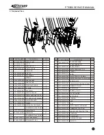
The radio is precision communication equipment. Please be careful when
assemble or disassemble the radio during service.
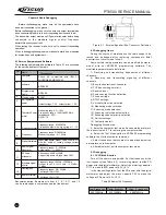
5.1 Installing/Removing the battery
pack
Match the 3 bulges of the battery pack
with the corresponding
at the rear
of the transceiver.
To install the battery pack:
slots
bottom
Figure
5.1-1
Removing the Battery Pack
To remove the battery pack, use your
thumb to press the belt clip, one side of
your index finger to press the release
button and then pull the battery away
from the radio.
5.2
INSTALLING THE ANTENNA
Screw the antenna into the connector at
the top of the transceiver by holding the
Button of the antenna and turn it
clockwise until secure.
5. 3
INSTALLING THE BELT CLIP
Match the grooves of the belt clip with
those on the rear of the battery. Then
press belt clip downwards to lock it in
place. Push the card by inserting your
nail or tool into the groove at the upper
part of the clip to remove the belt clip.
5. 4 Removing the Casing from the
Chassis
1
Remove the antenna and two
knobs;
2
Remove the two knob screws and a
antenna head screw;
3
Remove the two inner hexangular
aluminum alloy socket head screw
fixed at the bottom;
4
Insert the slotted screwdriver into
the groove at the bottom of the chassis
and apply force upwards to release the
aluminum alloy frame; and then hold
the aluminum alloy frame and draw it
out properly to remove it out of the
casing;
5
Plug the PCB winding displacement
connecting the main PCB and the
keyboard from the main PCB.
As shown in Figure 5.4-1
5. 5 Removing the main board from
the aluminum alloy frame
1
Remove the waterproof washer
at the top;
2
Remove the screws of the PTT
keypad and then remove the PTT
keypad;
3
Remove the screws on the PCB;
4
Melt the solder at the antenna
point with an electric soldering iron and
take off the main board.
As shown in Figure 5.4-1
5.6 Removing the keypad from the
surface casing
Remove the screws of the keypad to
detach the keypad from the surface
casing. As shown in Figure 5.6-1
Figure
5.1-2
Figure
5.2-1
Figure
5.3-1
Figure
5.4-1
Figure
5.5-1
Figure
5.6-1
12
Содержание PT6500
Страница 1: ...PROFESSIONAL TWO WAY RADIO PT6500 V071208 FM PORTABLE RADIO SERVICE MANOAL Welcome ...
Страница 33: ...PT6500 SERVICE MANUAL Figure 1 PT6500 Top Main Board Position Number Diagram 136 174MHz 32 ...
Страница 34: ...PT6500 SERVICE MANUAL Figure2 PT6500 Bottom Main Board Position Number Diagram 136 174MHz 33 ...
Страница 35: ...Figure 3 400 470MHz PT6500 Top Main Board Position Number Diagram 34 PT6500 SERVICE MANUAL ...
Страница 36: ...35 PT6500 SERVICE MANUAL Figure 4 400 470MHz PT6500 Bottom Main Board Position Number Diagram ...
Страница 37: ...Figure 5 PT6500 PTT Top Board Position Number Diagram 36 PT6500 SERVICE MANUAL ...
Страница 38: ...37 PT6500 SERVICE MANUAL Figure 6 PT6500 PTT BOTTOM Board Position Number Diagram ...


