


23
10
Technical data
Power supply by controller
230V~, 50Hz
Current consumed by
controller
0,06
4
A
Maximum rated current
5 (5) A
Controller protection rating
IP 20
5
Ambient temperature
0...50
C
Storage temperature
0...65
C
Relative humidity
5…85%
, without steam
condensation
Measuring range of
temperature sensors CT4
0..100
C
Measuring range of
temperature sensors CT4-P
and CT6-P
-35..40
C
Accuracy of temperature
measurements with sensors
CT4 and CT6-P
±2
C
Connectors
Screw
terminals
at
supply voltage side
–
2,5 mm
2
.
Screw
terminals
at
control voltage side
–
1,0 mm
2
.
Display
128x64 pix.
Dimensions
235x225x64 mm
Total weight
1,0 kg
Standards
PN-EN 60730-2-9
PN-EN 60730-1
Software class
A
Protection class
Suitable to build into
Class I devices
Type of disconnection
according to PN-EN 60730-2-
9
-
2Y
electronic
disconnection,
terminals: 3-4, 4-5.
- micro-disconnection
type 2B, terminals: 6-
7, 7-8, 9-7, 10-7, 11-7.
Pollution degree
2nd pollution degree
acc. to PN-EN 60730-1
11
Conditions of storage and transport
The controller cannot be exposed to direct
effects of weather, i.e. rain and sunlight.
Storage and transport temperature cannot
exceed the range of -
15…+65°C.
During
4
This is the current consumed by the controller itself.
The total current consumption depends on the devices
connected to the controller
.
5
After installing all cable clamps.
transport, the device cannot be exposed to
vibrations greater than those typical of
normal road transport.
12
The Controller installation
12.1
Environmental conditions
Due to the risk of fire is prohibited to use the
controller in explosive gas and dust
enviroment (e.g. coal). Controller should be
separated using appropriate enclosure. In
addition, controller cannot be used in the
presence of water vapor condensation and be
exposed to water.
12.2
Installation requirements
The controller should be installed by a
qualified and authorised fitter, in accordance
with the applicable norms and regulations.
The manufacturer bears no responsibility for
damages caused by failure to observe this
manual. The controller is to be built-in. The
controller cannot be used as a stand-alone
device. The temperature of the ambient and
the fitting surface cannot exceed the range
of 0…50°C.
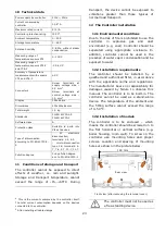
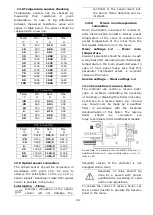
12.3
Installation of module
The controller is to be enclosed
–
which
means the controller should be screwed on to
the flat horizontal or vertical surface (e.g.
boiler housing, room wall). To screw on the
controller use mounting holes and proper
screws. Location and spacing of mounting
holes are shown in the picture below.
Rear view.
Front view (after removing the terminal cover).
The controller must not be used as
a free-standing device.
180 mm
Содержание ecoMAX360P1-C
Страница 6: ...6 ...
Страница 7: ...USER SETTINGS ecoMAX360P1 C ...
Страница 18: ...18 ...
Страница 19: ...19 INSTALLATION AND SERVICE SETTINGS ecoMAX360P1 C ...
Страница 42: ...42 ...
Страница 43: ...43 ...


