background image

4

-

11

description oF operating system

4

M55O4R6A

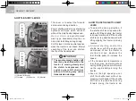
(1)  calibration switch

CAlIbRATION SwITCh

this switch is for calibration of shuttle 

lever and clutch pedal. if any calibra-

tion is required please contact 

KIOTI 

dealer at your earliest convenience.

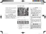
INSTRuMENT PANEl

(1) battery charge warning lamp

(2) engine oil pressure warning lamp

(3) 4wd operation indicator

(4) high beam indicator

(5) glow plug indicator

(6) turn signal lamp

(7) tachometer

(8) p.t.o on indicator 

(9) parking brake indicator 

(10) low Fuel level warning indicator 

(11) Fuel gauge

(12) hour meter

(13) coolant temperature gauge

(14) one side brake lamp

(15) coolant temperature warning lamp

M55O4P3A

symbols on the instrument panel come on when the key switch is turned to 

the "on" position. 

M55-유럽판-04.indd   11

2011-08-11   오전 11:58:09

Содержание RX6010C

Страница 1: ... since 1947 and has been designed with the finest materials under rigid quality control stan dards set forth by the KIOTI Engineering Department Knowledge of tractor operation is essential for many years of dependable service and reliability To help new owners familiarize themselves with the KIOTI RX6010C RX6010PC it is the policy of KIOTI tractor to provide an owners manual which includes helpful...

Страница 2: ...utside the European Community local laws will prevail Main protections on the tractors discussed in this manual DESCRIPTION NON CANOPY CANOPY 1 ROPS protection against overturning Yes Yes 2 FOPS protection against objects falling from above No Yes 3 OPS protection against penetration of objects from sides protection against hazardous chemicals No CategoryⅠ No CategoryⅠ ISO 3600 EU standards M55 유럽...

Страница 3: ...IFICATIONS DESCRIPTION OF OPERATING SYSTEM OPERATION 3 POINT HITCH MAINTENANCE STORAGE AND DISPOSAL TROUBLESHOOTING INDEX SECTION 1 2 3 4 5 6 7 8 9 10 TABLE OF CONTENTS 3 POINT HITCH IMPLEMENT AND LOADER OPERATION M55 유럽판 00 indd 3 2011 08 10 오후 2 16 22 ...

Страница 4: ...Decal mounting location 1 19 DeCALs 1 21 Cautions for decal maintenance 1 25 Precautions before operation 2 1 Vehicle identification number 2 2 TRACTOR SERIAL NUMBER 2 2 Engine SERIAL number 2 2 Transmission SERIAL number 2 2 Essential replacement parts 2 4 Oils and fluids 2 4 Filters 2 4 Belts and rubber parts 2 5 Other components 2 5 SPECIFICATIONS 3 1 General specifications 3 2 External dimensi...

Страница 5: ...shift lever 4 22 P T O shift lever 4 23 Clutch Pedal 4 24 Brake pedal 4 24 Steering wheel adjustment 4 25 Parking Brake Lever 4 25 IMPLEMENT LIMITATIONS 3 8 Standard size by implement 3 8 DESCRIPTION OF OPERATING SYSTEM 4 1 Exterior view 4 3 switch Mounting location 4 4 Key switch 4 6 Combination switch 4 7 Hazard lamp switch 4 8 4WD switch 4 9 P T O SWITCH 4 10 P T O selection switch 4 10 Calibra...

Страница 6: ...ER IF EQUIPPED 4 38 ANTENNA 4 38 CABIN Lamp 4 39 accessory 4 39 Sun Visor IF EUQIPPED 4 40 Recirculation fresh air mode 4 40 Heater and Air Conditioner 4 41 7 pin power output socket 4 44 tires Wheels and ballast 4 45 Inflation Pressure 4 46 TREAD 4 47 WHEEL TORQUE AND DIRECTION 4 49 Additional weight 4 50 Mass es and tire s 4 53 OPERATION 5 1 PRE OPERATION CHECK 5 2 OPERATING THE ENGINE 5 3 START...

Страница 7: ...ent with pto shaft 6 2 Operation tip for 3 point hitch elements 6 5 Adjustment of LIFT ROD 6 5 Adjustment of Top link 6 6 Precaution for installing How to use top link holes 6 6 Adjustment of stabilizer 6 7 dismounting the implement 6 7 Draw Bar and trailer 6 7 INSTALLING PTO SHAFT 6 9 Handling loader 6 11 fixation points for front end loader 6 12 Driving on slopes 6 13 Joystick lever 6 14 Joystic...

Страница 8: ...uel Filter S 7 21 REPLACING Air Cleaner Primary Element T 7 21 REMOVING WATER FROM FUEL FILTER T1 7 22 Bleeding brake fluid line T2 7 23 Checking Fuel Lines U 7 23 Adjusting fan belt tension V 7 24 Battery W 7 25 Checking intake air line X 7 27 Adjusting Toe in y 7 27 Checking Radiator Hose and Clamp Z 7 28 Power steering line AA 7 28 Air Conditioner BELT TENSION AB 7 29 Cleaning air conditioner c...

Страница 9: ...ner maintenance AS 7 46 STORAGE AND DISPOSAL 8 1 Tractor storage 8 2 Daily storage 8 2 Long term storage 8 2 Using tractor after storage 8 4 Usage and disposal 8 5 TROUBLESHOOTING 9 1 Engine Troubleshooting 9 2 Tractor Troubleshooting 9 4 INDEX 10 1 TABLE OF CONTENTS M55 유럽판 00 indd 9 2011 08 10 오후 2 16 22 ...

Страница 10: ... in harm serious injury or death to you or other persons if the warning is not heeded Follow the advice provided with the warning CAUTION This indicates that a condition may result in damage to your vehicle or its equipment if the caution is not heeded Follow the advice provided with the caution This mark indicates emphasis on notable characteristics of working procedures and information about tec...

Страница 11: ...gs Fuel level Headlight low beam Preheat Parking brake Headlight high beam Auto switch Battery charging condition Four wheel drive on Forward Engine oil pressure Fast Neutral Power take off clutch control off position Slow Reverse Power take off clutch control on position Differential lock Turn signal Hazard warning lights N F R M55 유럽판 00 indd 11 2011 08 10 오후 2 16 26 ...

Страница 12: ...M55 유럽판 00 indd 12 2011 08 10 오후 2 16 26 ...

Страница 13: ... When parking the tractor 1 11 When operating the P T O 1 11 When using the 3 point hitch 1 12 Safety precautions during servicing 1 12 Safety precautions when using the loader 1 16 Safety decal maintenance 1 19 Decal mounting location 1 19 DeCALs 1 21 Cautions for decal maintenance 1 25 SAFETY PRECAUTIONS 1 M55 유럽판 01 indd 1 2011 08 11 오전 11 55 31 ...

Страница 14: ...r 7 When starting the tractor make sure your path is clear of people to avoid accidents caused by sudden movements 8 Before making reverse movements with your tractor you should always check to see that the path is clear 1 It is recommended that you read and understand this entire manual before operation of your new trac tor Failure to do so could result in accidents injury or death 2 Only persons...

Страница 15: ...d Keep bystand ers away from the tractor while in operation 14 When getting on and off the trac tor hand holds and step plates should always be used This will help to prevent accidental slips trips and falls 15 Be sure to scrape off mud or soil from your shoes before mounting the tractor T66O104a 16 All persons using the tractor should have knowledge of its proper operation and should read this ma...

Страница 16: ...ing tractors with narrow tread widths For added stability you should adjust your rear wheel tread width see page 4 48 19 Before starting your tractor you should depress the clutch and make sure that all shift levers are in the neutral position and park ing brake is applied 20 For your safety a ROPS with a seat belt is recommended for all applications 1 Tread T66O106a T66O107a Always use seat belt ...

Страница 17: ... chensvit eyeprotec tion gloves etc 1 Avoid accidental contact with gear shift levers while the engine is run ning Unexpected tractor move ments can result in bodily injury or death 2 Do not park your tractor on a steep incline and remember to shut off the engine and P T O before dis mounting the tractor Precautions during operation When starting the engine T66O109a T66O108a T55O116a M55 유럽판 01 in...

Страница 18: ...he draw bar and front hitch receiver NEVER HITCH ANYTHING TO THE AXLE HOUS ING OR ANY OTHER POINT EX CEPT INDICATED POINTS Pull ing from any other location only in crease the risk of serious personal injury or death 1 Drawbar 2 Front Hitch Receiver M55O120A 6 Improper use of the draw bar even if correctly positioned can cause a rear overturn 7 Do not overload an attachment or towed equipment Use p...

Страница 19: ...nsporting Us H11O682A ing the proper adaptor parts attach the chain to the tractor draw bar support or other speci fied anchor location Provide only enough slack in the chain to per mit turning See your Dealer for a chain with a strength rating equal to or greater than the gross weight of the towed machine 11 If the front of the tractor tends to rise up when heavy implements are attached to the th...

Страница 20: ...actor can become dangerous to you and bystanders Overload ing your tractor or using unsafe equipment can also be danger ous and should be avoided Refer to the Specifications of Implement Limitation which out lines the maximum load for safe tractor operation 18 Driving forward out of a ditch or steep inclines can cause the tractor to tip over backwards To avoid this you should back out of these pos...

Страница 21: ...under the tractor s weight The risk of tractor upset is even higher when the ground is loose or wet T66O115a 2 Always slow the tractor before turning Turning at high speed may tip the tractor over or cause a loss of control 1 Lock the brake pedals together when traveling at road speeds Brake both wheels simultaneously when making an emergency stop Uneven braking at road speeds could cause the trac...

Страница 22: ...ractor may run out of control 8 Avoid sudden movements of the steering wheel as this can cause a loss of control of the tractor This risk is especially great when traveling at road speeds 9 Do not operate an implement while the tractor is on the road Lock the three point hitch in the raised position 10 When towing other equipment use a safety chain and place an SMV emblem on it as well 11 When dri...

Страница 23: ...e 3 Before installing or using P T O driven equipment read the man M55O109A ufacturer s manual and review the safety labels attached to the equip ment WARNING Before driving an implement through the PTO always make sure that all bystanders are well away from the tractor When using the PTO drive with a stationary tractor always make sure that the gears are in neutral and that the parking brake is a...

Страница 24: ...d place chocks behind and in front of the rear wheels Stay clear of all rotat ing parts 5 Do not attach a P T O driven imple ment if the implements safety shields are damaged or not in place Rotating shafts are an en tanglement hazard M55O111A In order to service your tractor you must park it on a flat level surface set the parking brake place the gear shift lever in neutral and stop the engine 1 ...

Страница 25: ... cool slowly rotate the cap to the first stop and allow sufficient time for excess pressure to escape After all the pressure is released remove the cap completely If your tractor is equipped with a coolant recovery tank add coolant there rather than to the radiator T66O125a T66O126a M55O114a 7 If the tractor must be lifted for servicing take it to a suitably equipped workshop 8 Carry out the follo...

Страница 26: ...spaces and would be all too easily removed or ef faced during normal operation of the tractor M55O115a 12 When working with your trac tors electrical components you must first disconnect the battery cables 13 TO ENSURE THAT THERE ARE NO ACCIDENTS FROM SPARKS YOU MUST FIRST DISCONNECT THE NEGATIVE BATTERY CABLE T66O127a Apply the jack lift to the lifting points according to the type of operation an...

Страница 27: ... fluid under pressure has sufficient force to penetrate skin causing serious personal injury Be sure to release all residual pressure Before dis connecting hydraulic lines Before adding pressure to the hydraulic system make sure that all connections are tight and that all lines pipes and hoses are free of damage T66O129a T66O128a 19 FLUID ESCAPING FROM PIN HOLES MAY BE INVISIBLE DO NOT USE HANDS T...

Страница 28: ...rs and battery T66O131a 1 Never let anyone get in the loader and use the loader as a worksta tion Otherwise it may lead to a fatal injury or even death H11O102a Safety precautions when using the loader 2 Do not stand under the lifted load er or get close to it Also lower the loader arm onto the ground be fore leaving the tractor Otherwise it may lead to a fatal injury or even death H11O103a M55 유럽...

Страница 29: ...a 4 Never carry a big object with the loader unless a proper implement is attached Keep a carried object low during driving Otherwise it may lead to an injury or even death H11O105a 5 When attaching or detaching the loader fix all parts which are con nected to the bucket and boom The bucket or boom can be acci dentally dropped down leading to an injury or even death H11O106a M55 유럽판 01 indd 17 201...

Страница 30: ...ms or attach ment to contact electrical power lines Electrocution will cause seri ous injury or death H11O107a 7 Keep bystanders away No riders Otherwise it may lead to a fatal injury or even death H11O108a M55 유럽판 01 indd 18 2011 08 11 오전 11 55 48 ...

Страница 31: ...1 19 SAFETY PRECAUTIONS 1 Safety decal maintenance Decal mounting location M55O119A Safety decal maintenance Decal mounting location M55 유럽판 01 indd 19 2011 08 11 오전 11 55 51 ...

Страница 32: ...1 20 RX6010C RX6010PC M55O113A M55 유럽판 01 indd 20 2011 08 11 오전 11 55 54 ...

Страница 33: ...Implements that are designed to use the 3 point hitch should only use the 3 point hitch To prevent severe and deadly injuries during P T O operation 1 All protective components should be in place 2 Do not let your hands feet and clothes come near the implement 3 When disengaging an implement from the P T O stop the engine in advance When repairing or servicing the tractor or its part depress the b...

Страница 34: ...y decals 2 Make sure to follow the driving instruc tions specified in the manual and decals for safe driving 3 Do not modify any part of the vehicle 4 Never attach an implement with exces sive capacity other than the standard implements KIOTI has no responsibility for problems oc curred by negligence of a driver WARNING 1 Turning on the A C for an extended period of time makes the air stuffy in th...

Страница 35: ...g conditions 1 Driving at a high speed 2 Driving on a hill or sharp curve 3 Working with an implement such as a plow at a high speed 4 Working with the loader attached KIOTI has no responsibility for problems occurred by negligence of a driver 1 For the tractor equipped with the ROPS make sure to wear the seat belt all the time For the tractor not equipped with the ROPS never wear the seat belt 2 ...

Страница 36: ... bucket onto the ground before stopping the engine Otherwise it can cause an accident or injury CAUTION 1 Using parking brake Before leaving the vehicle park the vehicle and apply the parking brake Depress the brake pedals before leaving the vehicle 2 Shifting Depress the clutch pedal fully before shifting the gear lever Otherwise abnormal noise is produced from the gears which causes damage Disen...

Страница 37: ...use a solvent such a thinner or acetone since it can ruin the decals Do not spray high pressure water directly onto the decal The decal may fall off the trac tor CAUTION If a decal is damaged or lost contact your local KIOTI deal er immediately to install a new decal Make sure to attach the decal to the correct position cleanly without bubbles after cleaning its mounting surface If a decal is atta...

Страница 38: ...MEMO MEMO M55 유럽판 01 indd 26 2011 08 11 오전 11 56 02 ...

Страница 39: ...on number 2 2 TRACTOR SERIAL NUMBER 2 2 Engine SERIAL number 2 2 Transmission SERIAL number 2 2 Essential replacement parts 2 4 Oils and fluids 2 4 Filters 2 4 Belts and rubber parts 2 5 Other components 2 5 2 2 M55 유럽판 02 indd 1 2011 08 10 오후 2 15 27 ...

Страница 40: ...Number Plate This number is to identify the vehicle and its plate is attached on the front right side of the front axle frame M55O206A 1 Engine Serial Number R60O204B It is stamped on the range shift lever case on the left side of the tractor The engine number is stamped on the mounting surface of the injection pump R60O205B M55 유럽판 02 indd 2 2011 08 10 오후 2 15 30 ...

Страница 41: ...be sure to see your KIOTI dealer For service contact the KIOTI dealership from which you purchased your tractor or your local authorized KIOTI dealer When in need of parts be prepared to give your dealer both the tractor and engine serial numbers Before using non KIOTI approved implements contact your nearest dealer regarding safety application of the implement Tractor Model Name To be filled in b...

Страница 42: ...ts If oil or fluid is insufficient contami nated or degraded it can cause poor performance incorrect operation and seized parts of the tractor lead ing to malfunctions Regularly add or change the fluid specified on the right to keep the tractor in perfect condition Essential replacement parts Oils and fluids ITEM SPECIFICATION CAPA Engine oil SAE 15W40 2 03 U S gal 7 7 L Trans mission fluid DAEDON...

Страница 43: ... Therefore regularly check or replace those items to pre vent the failure The battery condition is very impor tant for engine start performance es pecially in winter Therefore make sure to check its condition daily H11O207a Belts and rubber parts Other components NO PART NO DESCRIPTION QTY 1 E6305 72533 Fan Belt 2 2 E7220 72611 A C Belt 1 NO PART NO DESCRIPTION QTY 1 C7910 42204 Battery 1 M55 유럽판 ...

Страница 44: ...MEMO MEMO M55 유럽판 02 indd 6 2011 08 10 오후 2 15 30 ...

Страница 45: ...pecifications 3 3 noise levels as perceived by the operator 3 5 VIBRATION LEVELS OF THE TRACTOR EXPOSITION TO VIBRATIONS 3 5 TRAVELING SPEED 3 7 IMPLEMENT LIMITATIONS 3 8 Standard size by implement 3 8 SPECIFICATIONS 3 3 M55 유럽판 03 indd 1 2011 08 11 오전 11 56 27 ...

Страница 46: ...ont wheel tread E2 Rear wheel tread Item RX6010C RX6010PC remark 1 Overall length A1 158 3 4 020 2 Overall length A2 145 7 3 700 3 Overall width B 69 1 1 755 USA 73 8 1 875 AU EU 4 Overall height C 102 8 2 610 USA 103 5 2 630 AU EU 5 Wheel base D 82 7 2 100 6 Tread E1 54 1 1 375 USA 58 1 1 475 AU EU 7 Tread E2 54 1 1 375 USA 58 7 1 490 AU EU 8 Ground clearance F 16 5 420 General specifications Ext...

Страница 47: ... wet disc clutch Transmission Shuttle Synchromesh shuttle Power shuttle Main Synchromesh 4 Range Constant mesh 3 Speeds 12 x 12 Ground speed Tire for agriricultural AG m h km h Forward 1 16 19 61 1 86 31 56 USA 1 20 20 33 1 83 32 72 AU EU Reverse 1 14 19 28 1 83 31 03 USA 1 18 19 99 1 90 32 17 AU EU 4 wheel drive Hydraulic dog clutch USA Hydraulic multi wet disc clutch AU EU Brake Multi wet disc c...

Страница 48: ... 2 3 point hitch SAE Category Ⅱ Max lifting capacity lbs kg 24 in 61 cm Behind 3 594 1 630 Lower link end 4 575 2 075 Rear Type Independent P T O hydraulic multi plate disc clutch P T O shaft SAE 1 3 8 6 splines In compliance with A S A E standards Speed P T O rpm engine rpm 1st 540 2 444 2nd 1 000 2 493 Min turning radius with one rear wheel braked in mm 118 9 3 020 USA 122 4 3 110 AU EU Weigh In...

Страница 49: ...mitted to the body as a whole depend on different parameters some of them relating to the machine others to the terrain and many specific for the operator The prevailing parameters are the type of terrain or work surface and the ground speed Vibrations cause discomfort for the operator and in some cases put his her health and safety at risk Make sure that the tractor is in good condition and that ...

Страница 50: ... measured on seats in aws aws correct weighted value of the vibration acceleration m s2 Operator s Vibration level Seat type Directive of The European Parliament and of the Council Light weight operator Heavy weight opeartor W08SSS 78 764 EEC 0 83 m s2 0 75 m s2 M55 유럽판 03 indd 6 2011 08 11 오전 11 56 29 ...

Страница 51: ...2 49 4 01 2 49 4 01 2 45 3 94 2 45 3 94 Middle 1 3 28 5 28 3 28 5 28 3 22 5 19 3 22 5 19 2 4 32 6 96 4 32 6 96 4 25 6 84 4 25 6 84 3 5 46 8 78 5 46 8 78 5 36 8 63 5 36 8 63 4 7 00 11 26 7 00 11 26 6 88 11 07 6 88 11 07 High 1 9 28 14 93 9 28 14 93 9 12 14 68 9 12 14 68 2 12 23 19 69 12 23 19 69 12 03 19 36 12 03 19 36 3 15 43 24 84 15 43 24 84 15 18 24 43 15 18 24 43 4 19 61 31 56 20 33 32 72 19 2...

Страница 52: ...ng depth Not use Do not use 3 point hitch backhoe 3 Mid Mower Max width Not use 4 Tiller Max width Not use 5 Box Blade Max width Below 84 0 2 134 6 Rear Blade Max width Below 84 0 2 134 Use it only to lowest top link hole 7 Rotary Cutter Max width Below 84 0 2 134 8 Aerator Max width Below 84 0 2 134 9 Landscape Rakes Max width Below 84 0 2 134 in mm M55 유럽판 03 indd 8 2011 08 11 오전 11 56 30 ...

Страница 53: ... 14 Turn Signal Lamp 4 15 Glow Plug Indicator 4 15 Parking brake warning lamp 4 15 PTO Indicator 4 16 4WD indicator 4 16 Low fuel level warning indicator 4 16 Brake one side lamp 4 17 forward Indicator 4 17 neutral indicator 4 18 reverse indicator 4 18 Coolant Temperature Warning Lamp 4 18 OPERATING THE CONTROLS 4 19 MAIN SHIFT LEVER 4 21 RANGE GEAR SHIFT LEVER 4 21 Shuttle shift lever 4 22 P T O ...

Страница 54: ...nce 4 34 Rear window 4 35 side window 4 35 Working Light 4 36 Wiper 4 36 RADIO CASSETTE CD PLAYER IF EQUIPPED 4 38 ANTENNA 4 38 CABIN Lamp 4 39 accessory 4 39 Sun Visor IF EUQIPPED 4 40 Recirculation fresh air mode 4 40 Heater and Air Conditioner 4 41 7 pin power output socket 4 44 tires Wheels and ballast 4 45 Inflation Pressure 4 46 TREAD 4 47 WHEEL TORQUE AND DIRECTION 4 49 Additional weight 4 ...

Страница 55: ...Exterior view M55O4R1A 1 Working Lamp FRT RR 2 Wiper 3 Rear View Mirror 4 Turn Signal Lamp FRT RR 5 Step 6 Bonnet 7 Head Lamp 8 Top Link 9 Lift Rod 10 Lower Link 11 Draw Bar 12 Backup lamp 13 License plate bracket M55 유럽판 04 indd 3 2011 08 10 오후 2 21 01 ...

Страница 56: ...RX6010C RX6010PC switch Mounting location 1 Key Switch 2 Combination Switch 3 Hazard Lamp Switch 4 Driving Mode Selection Switch 5 Instrument Panel MANUAL M55O4K5A M55 유럽판 04 indd 4 2011 08 11 오전 11 57 57 ...

Страница 57: ...DESCRIPTION OF OPERATING SYSTEM 4 1 Key Switch 2 Combination Switch 3 Hazard Lamp Switch 4 Driving Mode Selection Switch 5 Instrument Panel POWER SHUTTLE M55O4K4A M55 유럽판 04 indd 5 2011 08 11 오전 11 57 59 ...

Страница 58: ...ds in cold weather NOTE B When the key switch is in position B the engine and all electrical devices in the vehicle are turned off However flasher lights and turn signal lights can be operated along with their indication lamps on the dash board ACC C When the key switch is turned to the position C brake lights flasher lights and turn signal lights can be operated D The position D indicates the ON ...

Страница 59: ...in any direc tion Also be careful not to leave the tractor unattended with the key in the tractor The horn turn signal lamp and hazard lamp can be operated without the key inserted NOTE The head light switch can be operated only while the key switch is in ON position Turning the head light switch clockwise one click will illuminate the low beam head lights while turning it one more click will illu...

Страница 60: ...ch Hazard lamp switch 1 Hazard Lamp Switch A ON B OFF M55O4L1A M55O4L2A The turn signal light lever is not the self return type Therefore make sure to return the lever manually after turning the vehicle The turn signal lamps can be op erated without the key inserted NOTE This switch can be used to warn other vehicles when malfunction oc curs in the tractor while driving on a public road Pressing t...

Страница 61: ...t shift or impact at times in this case For safe driving engage the 4WD when the trac tor is stationary The 4WD should not be used on a paved road as tires can be worn faster and could cause damage to front axle CAUTION To engage the 4WD press the switch up To disengage it return the switch The 4WD function can be used un der the following conditions 1 If high traction is needed in a wet area 2 Wh...

Страница 62: ...d Always keep the PTO driving part clean Also check the PTO cover is closed while PTO is in operation Disengage the PTO while driv ing the tractor on the public road Be careful not to get your hand foot cloth or hair into any driving part while the PTO is in operation You can be se verely injured or killed Make sure that no one is around the tractor and imple ment while the PTO is in op eration CA...

Страница 63: ...ng Lamp 2 Engine Oil Pressure Warning Lamp 3 4WD Operation Indicator 4 High Beam Indicator 5 Glow Plug Indicator 6 Turn Signal Lamp 7 Tachometer 8 P T O On Indicator 9 Parking Brake Indicator 10 Low Fuel Level Warning Indicator 11 Fuel Gauge 12 Hour Meter 13 Coolant Temperature Gauge 14 One Side Brake Lamp 15 Coolant Temperature Warning Lamp M55O4P3A Symbols on the instrument panel come on when th...

Страница 64: ... the remain ing fuel level after the key switch is turned to the ON position F Fuel is fully filled E Replenish the fuel tank If driving is continued with the needle below the position E air may enter the fuel supply system In this case bleed the system For detailed in structions refer to Bleeding fuel sys tem in the chapter Maintenance Make sure to use only correct fuel as the engine can be dam a...

Страница 65: ...E ENGINE IMMEDIATELY IN STEAD REDUCE THE WORK LOAD TO COOL DOWN THE ENGINE BEFORE STOPPING THE ENGINE Make sure to keep the front grill clean so that air is sucked through it freely for fast cool ing CAUTION This lamp comes on when the en gine oil pressure or oil level is low This lamp is turned On when the starting switch is turned On before starting the engine but turned Off after starting the e...

Страница 66: ...ting the engine If this warning lamp comes on while driving the charging system such as the alternator is malfunctioning Therefore turn off all electrical devices and have the tractor checked by your local KIOTI Dealer or workshop as soon as possible CAUTION Head light high beam lamp This lamp comes on in blue when the high beam head light is switched on Driving with high beam head light disturbs ...

Страница 67: ...n case the auto pre heating kit is installed this indicator comes on 8 seconds when the key switch is turned to the ON position In case of basic model this indicator comes on when the key is held in PRE HEAT position by op erator If this indicator is ON even with the parking brake released have the tractor checked by your local KIOTI dealer or workshop immediately If you drive with parking brake l...

Страница 68: ...ck turn mode is in operation M55O4P6A The durability of the axle can be deteriorated if only one brake pedal is depressed while the 4WD is activated CAUTION This indicator shows the PTO en gagement condition When the PTO is engaged this indicator comes on When the PTO clutch is disengaged this indicator goes off set the PTO switch to the OFF position in order to start the engine CAUTION If the fue...

Страница 69: ...n a public road or at a high speed never use only one brake pedal The tractor can roll over While the brake one side lamp is illuminated the brake pedals are not interlocked and only one brake pedal can be depressed accidentally Make sure to set the pedal lock to the Lock position in a normal condition IMPORTANT If the shuttle lever is in forward posi tion this lamp turns in green forward Indicato...

Страница 70: ...ever is in reverse posi tion this lamp turns in green reverse indicator M55O4Q6A M55O4Q7A If the coolant temperature keeps 239 115 for more than 5 sec onds buzzer is heard and lamp is turned on Stop the engine contact a KIOTI dealer immediately Coolant Temperature Warning Lamp M55O4R8A M55 유럽판 04 indd 18 2011 08 11 오전 11 58 19 ...

Страница 71: ...TROLS 1 Hand Throttle Lever 2 Shuttle Shift Lever 3 Clutch Pedal 4 Steering Column Tilt 5 Brake Pedal L 6 Brake Pedal R 7 Main Shift Lever 8 Range Shift Lever 9 Joy stick Lever 10 Double Acting Lever MANUAL M55O4Q9A M55 유럽판 04 indd 19 2011 08 11 오전 11 58 22 ...

Страница 72: ...tle Shift Lever 3 Clutch Pedal 4 Steering Column Tilt 5 Brake Pedal L 6 Brake Pedal R 7 Main Shift Lever 8 Range Shift Lever 9 Joy stick Lever 10 Double Acting Lever 11 P T O Change Lever POWER SHUTTLE M55O4S2A M55 유럽판 04 indd 20 2011 08 11 오전 11 58 25 ...

Страница 73: ...the tractor is completely stopped by depress ing the clutch pedal If the lever is not moved freely or makes abnormal noise put the lever in the neutral po sition depress the clutch pedal and then try to shift the lever 1 Range Gear Shift Lever L Low Speed N Neutral M Middle Speed H High Speed Make sure to shift the range gear shift lever with the clutch pedal depressed and the trac tor stationary ...

Страница 74: ...ing slightly the tractor is driving forward and if the shuttle shift lever is pulled backward with lifting slightly the tractor is driving reverse At initial starting control the shuttle lever with the engine rpm decreased When the tractor is started to move depress the foot throttle pedal to increase the speed If the transmission temperature is low there may be starting shock during shifting Make...

Страница 75: ...follow The model for USA has only one shift range of P T O 540 RPM with a 2 444 RPM engine rate 1 000 RPM with a 2 493 RPM engine rate rpm Gears 1st 2nd P T O RPM 540 1 000 To prevent injuries When connecting discon necting or cleaning any P T O driven equipment stop all rotating parts stop the engine and disengage the P T O CAUTION Never rest your foot on the clutch pedal during driving The clutc...

Страница 76: ...d abruptly driv ing off CAUTION Never put your foot onto the clutch pedal during driving The clutch disc can be worn prematurely Be sure to depress the clutch pedal fully when shifting Oth erwise the shift gear can be broken IMPORTANT Brake pedal 1 Make sure to link the left and right brake pedals as shown in the figure while driving on a road The tractor can roll over if depressing only one brake...

Страница 77: ...s activated WARNING Steering wheeladjustment The angle of the steering wheel can be adjusted for the driver s comfort Hold the steering wheel with both hands depress the tilt pedal lightly and then adjust the position of the steering wheel as desired 1 Steering Wheel Tilt Pedal A Lowering B Lifting M55O4L9A Do not adjust the tilt steering while driving An accident can occur unexpectedly CAUTION Pa...

Страница 78: ...up To release the parking brake pull up and press the thumb button Then while holding the button in lower the brake lever EU only FOOT THROTTLE 1 Foot Throttle A Depress M55O4E9A The foot throttle is mainly used dur ing driving on a road while the hand throttle lever is mainly used in work field To avoid possible injury death or loss of property from a ma chine runaway With the engine off the trac...

Страница 79: ...e releasing the pedal disengages the differential lock Use this system under the following conditions Do not use the hand throttle le ver while driving on the public road Otherwise it can lead to an accident as it becomes hard to decelerate the tractor rapidly CAUTION 1 When any wheel slips and the tractor does not move in the field 2 When it is hard to escape a soft or muddy field The differentia...

Страница 80: ...een the seat and the slides when ad justing the seat position You can get injured unexpectedly CAUTION To adjust the seat position pull the lever 1 to upward under the front of the seat slide the seat to the desired position and then release the lever Make sure that the seat is firmly fixed by moving it gently after adjustment The seat height can be adjusted to fit to the driver Turning the handle...

Страница 81: ...cushion lighter while turning it to the direction makes the cushion heavier The seat belt is semi automatic self retracting type Make sure to fasten the seat belt before driving To dis engage the seat belt press its red release button Make sure that the seat belt is not twisted It cannot work properly leading to a danger ous situation The seat belt should go around your body as low as possible not...

Страница 82: ...erating range of the lever For detailed information refer to 3 point hitch control in Chapter 5 1 Draft Control Lever A Lifting B Lowering The draft function can be used for the plow which is installed to the lower link lifting arm If the plow is applied with excessive draft the lifting arm is automatically raised to reduce the draft and then returned to its original This is called Draft Function ...

Страница 83: ...function at light load For detailed information refer to Draft control in Chapter 5 Turning the knob counterclockwise increases the lowering speed while turning it clockwise decreases the lowering speed Also turning it clock wise to its end can fix the implement to a certain position Lifting Arm Lower Link Speed Control KNOB This knob does not control the lifting speed of the lower link NOTE 1 Low...

Страница 84: ...h hydraulic pressure For detailed information see Opera tion in Chapter 5 Put the detent valve if equipp ed operating lever into the neutral position when the hydraulic implement is not in use If the detent valve is kept in the operating position for an extended period of time the relief valve is kept open and the temperature of the hy draulic fluid rises leading to damage of various hydraulic par...

Страница 85: ...bin System Interior devices 1 Speaker 2 Heater Air Conditioner Air Grill 3 Recirculation Filter 4 Heater Air Conditioner Switch 5 Interior Lamp 6 Air Source Mode Lever 7 Inside Rearview Mirror M55O4N1A M55 유럽판 04 indd 33 2011 08 11 오전 11 58 43 ...

Страница 86: ...ows as well as outside rearview mirrors on both sides to provide a clear and wide rear view 3 The cabin can be kept comfortable and pleasant by operating the air conditioner and heater Entrance 1 Button 2 Door Handle 1 Work Light F 2 Work Light R 3 Antenna 4 Wiper 5 Outside Rearview Mirror 6 Door Handle M55O4I1B 4 The cabin structure is safe as it is verified by the ROPS Roll Over Protection Struc...

Страница 87: ...he button on the rear window handle lightly to open the rear win dow in the cabin To close it hold the handle and pull it gently H11O482a Rear window 1 Handle of rear window 2 Button The rear window may not be opened due to an implement Make sure to check if there is enough space to open the win dow to prevent damage and breakage by an implement Never drive the tractor with the door open An accide...

Страница 88: ...on the switch marked front to the ON position The key switch should be positioned to the ON position to power the working lights Do not drive the tractor on a road with the work lights ON at night The approaching or following vehicle s visibility can be dis turbed which is very danger ous for both drivers In this case use the hazard lamps WARNING 1 Wiper Operating Switch Front 2 Wiper Front Wiper ...

Страница 89: ... you are trying to spray the washer fluid when its tank is empty Therefore make sure to check the fluid level before driving Spray enough washer fluid and operate the wiper if there is dirt on the window When operating the wiper while it is frozen to the window its fuse can be blown In this case op erate the wiper after increas ing the cabin temperature enough to defrost the wiper WARNING 3 The wa...

Страница 90: ...dio sys tem is too high the driver can be distracted resulting in an accident CAUTION ANTENNA 1 Antenna Radio antenna Check the contact and angle of the antenna in case of poor signal recep tion M55O4I7A Inserting CD Cassette tape Inserting a CD cassette tape oper ates the CD cassette player auto matically For detailed information refer to the owner s manual for the audio system M55 유럽판 04 indd 38...

Страница 91: ... Rear view Mirror 1 Inside Rearview Mirror The cabin is equipped with the inside rearview mirror for the driver s con venience Adjust the angle of the mirror before driving for a clear rear view M55O4N6A Cigarette lighter Press and release the cigarette lighter When it is heated to the specified level it pops out automatically Then it is ready to be used It can also be used as a power source It is...

Страница 92: ...esh air when the air condi tioner is in operation Pushing the vent lever to A opens the vents and draws fresh air from outside Pushing the vent lever to B closes the vents to recirculate air in the cabin M55O4N8A U WARNING This cabin is not designed for spraying chemicals and can not block polluted outside air from entering WARNING Sun Visor IF EUQIPPED 1 Sun Visor Pull it down to block the sunlig...

Страница 93: ...al temperature rises rapidly in hot weather or on a sunny day Use the fresh air mode in normal conditions and use the air recir culation mode only if necessary Continued operation of the air recirculation mode can cause the inside to become stuffy causing headaches drowsiness or frost on the windows Do not operate the recirculation mode for an extended period of time WARNING H11O493A The fan speed...

Страница 94: ...ents in the front and 4 vents on the left and right When the dial is turned to the Defrost position air comes out from 4 vents in the front to defrost the wind shield H11O498A The desired temperature can be set by adjusting this dial Warm air flows out by turning it clockwise Red and cool air flows out by turning it coun terclockwise Blue The temperature control dial only con trols the amount of a...

Страница 95: ...vents during long hours of driving turn off the air conditioner set the fan speed control dial to the 4th speed drive for 5 to 10 min utes and then turn on the air conditioner CAUTION Make sure to operate the air conditioner once or twice a month in winter season to pre vent refrigerant leakage and facilitate the compressor lubri cation for durability of the A C components CAUTION A C refrigerant ...

Страница 96: ...eration Turn off the air conditioner for better engine power when the work load rapidly increases When the tractor is stationary and being used in high load work reduce the A C opera tion period as the engine may be overheated Make sure to operate the air conditioner once or twice a month in winter season to pre vent refrigerant leakage and facilitate the compressor lubri cation for durability of ...

Страница 97: ...ad with an implement which has ex terior lamps such as a trailer make sure to turn on those lamps by connecting them to the 7 pin socket in order to prevent an accident Make sure to check for proper operation after connecting the 7 pin socket to the trailer It may not operate depending on the trailer specifications Con sult your local KIOTI Dealer for this issue WARNING Do not use tires larger or ...

Страница 98: ...aximum when using the front end loader or front suitcase weights If tires with a different size from the ones already in use are in stalled contact the KIOTI dealer for the front rear wheel speed ratio Improper front rear wheel speed ratio can result in exces sive wear of the tires NOTE T46w031a Do not weld or apply heat to the tire rim or disc The tire can explode due to the rapidly in creased pr...

Страница 99: ...th rim to the disk to suit the type or condition of work 1 Bolt 2 Rim Bolt 3 Disc Never operate tractor with a loose rim wheel or axle Always tighten nuts or bolts to the specified torque Make sure to frequently check that all these parts are firmly tightened Make sure to perform inspec tion daily WARNING M55 유럽판 04 indd 47 2011 08 11 오전 11 58 59 ...

Страница 100: ...4 48 RX6010C RX6010PC Front rear tire tread STANDARD AFTER ADJUSTMENT Front Wheel Rear Wheel M55O4R7A M55 유럽판 04 indd 48 2011 08 11 오전 11 59 01 ...

Страница 101: ...0 23 kgf m 144 7 166 3 lb ft Rear 274 6 318 7 N m 28 32 5 kgf m 202 5 235 1 lb ft WHEEL TORQUE AND DIRECTION front REAR wheelinstallation pattern Use tires approved by KIOTI only Assemble the tire as shown in the figure Contact your local KIOTI Dealer if it is necessary to change the tire specification or installation method WARNING FRONT AND REAR wheel bolt AND NUT torque RIM bolt and nut torque ...

Страница 102: ... wheels remove the extra front weight Additional weight Additional front weight M55O4J9B If the front tires are excessively load ed and it becomes hard to steer the tractor the tires can be worn faster and the durability of the front axle can be deteriorated For agricultural tires make sure to install them with their arrow marks on their side pointing to the front driving direction The tire is cor...

Страница 103: ...ealer Attach only required amount of weight Otherwise the life of the axle or wheel can be shortened IMPORTANT Additional weight might be needed for transporting heavy implements Reduce the speed regardless of additional weight when driv ing on a bumpy or rough road with the implement lifted The tractor can roll over CAUTION 1 H11O4E1a 1 Rear Weight Additional rear weight IF EQUIPPED The rear weig...

Страница 104: ...y a part of the rim is exposed resulting in corrosion For a tire with a tube fill it up to 90 of its level Additional liquid type weight If the liquid ballast is used inflate the tire 0 14bar 2psi more than the specified pressure This is to compensate for the ventilation symptom which occurs while the tire is moving The liquid injection should be performed only by a qualified service personnel For...

Страница 105: ...f this these mass es among the axles Maximum permissible vertical load on the coupling point daN AAH ABM Front wheel Agri 11 2 20 8PR 1 120 2 100 42 750 320 70 R20 1 150 2 100 42 Agn 300 70 R20 1 215 2 100 42 Turf 31x13 5x15 8PR 1 180 2 100 42 Ind 12 5 80 18 10PR 2 135 2 100 42 Rear wheel Agri 14 9 30 8PR 1 930 2 900 58 420 70 R28 2 070 2 900 58 Agn 420 70 R30 2 120 2 900 58 Turf 44x18x20 4PR 1 55...

Страница 106: ...MEMO MEMO M55 유럽판 04 indd 54 2011 08 11 오전 11 59 04 ...

Страница 107: ... How to drive 5 9 Parking 5 13 Turning 5 14 Driving on slopes 5 15 precautions when coming in and out of WORK FIELD 5 15 precautions while driving on the road 5 16 LOADING AND UNLOADING 5 17 Precautions when using power steering 5 17 3 point hitch control SYSTEM 5 19 Draft control 5 21 REMOTE hydraulicS 5 22 Connecting and disconnecting implement 5 25 5 M55 유럽판 05 indd 1 2011 08 11 오전 11 56 56 ...

Страница 108: ...ease the idling time in cold weather 3 Do not drive the tractor at the max imum speed on a road 4 Never apply excessive load during work 5 Idle the engine at a low speed for 2 to 3 minutes before stopping it Driving a new tractor at a high speed or under heavy load can affect its du rability Make sure to run the tractor at the proper work load and speed for the initial operation of 10 to 20 hours ...

Страница 109: ...covered under warranty Never try to start the engine for over 10 seconds consecu tively to protect the start mo tor and battery from damage IMPORTANT When the parking brake is en gaged the parking brake lamp on the instrument cluster illu minates When releasing it the parking brake lamp is turned off NOTE Make sure that the brake ped als are fully depressed before pulling the parking brake lever u...

Страница 110: ...3 Place the PTO switch to the OFF position It cannot be started while the PTO is engaged 4 Set the main range and shuttle shift levers in the neutral position Make sure that no one is near the implement or behind the tractor WARNING 7 Set the hand throttle lever to the Slow position In case of cold weather you may adjust it to Fast for easier starting 8 Depress the clutch pedal It can not be start...

Страница 111: ...s with the key switch in the ON position The post heating is a function to keep the glow plugs activated for approx 15 seconds after the engine is started in order to enhance the engine combus tion performance and to reduce harmful emissions right after en gine start NOTE warning lamps come on when the key is in ON position before the engine start 10 When the engine is started re lease the key The...

Страница 112: ... local KIOTI Dealer 2 If the charge warning lamp 3 does not go off in 4 to 5 seconds after the engine is properly started it means that the battery is not be ing charged Have the charging system such as the battery and alternator inspected 3 Refer to Instrument panel in chapter 4 for detailed information about other indicators and lamps The engine can be severely damaged if it is ran with the oil ...

Страница 113: ...rted Therefore using these compo nents without the engine start ed can discharge the battery IMPORTANT It is recommended always to warm up the engine before driving in order to maintain the durability of the engine Before warming up the engine make sure that each part in the engine is properly lubricated and each hydraulic part is in a perfect condition in order to prevent malfunction in the engin...

Страница 114: ...ccordance with each ambient temperature Ambient temperature Warm up period 0 or warmer 5 10 minuites 0 10 10 20 minutes 10 20 20 30 minutes 20 or colder 30 minutes or more Warming up the engine exces sively increases fuel consump tion and affects the durability of the tractor negatively Never leave the tractor unat tended while warming up It can cause fire and an accident WARNING Be sure to apply ...

Страница 115: ...r body with the discharged battery Make sure to connect the clip to the body part without paint 6 Start the engine of the tractor with the normal battery 7 Start the engine of the tractor with the discharged battery 8 Disconnect the black cable from the negative battery terminals of both of the tractors 9 Disconnect the red cable 10 Run the engine for at least 30 minutes to charge the discharged b...

Страница 116: ...dal at a high speed the trac tor can lose its balance and be overturned WARNING Do not adjust the tilt angle of steering wheel while driving You could lose the handle of your tractor causing an acci dent WARNING Always wear the seat belt when cap is installed The seat belt should go around your pelvis or as low as pos sible not your waist or abdo men Otherwise the seat belt cannot protect you prop...

Страница 117: ...ement M55O547A 6 Increase slowly the engine RPM from idle speed to medium speed 1 Hand Throttle Lever Slow Fast 7 Release the parking brake 1 Parking Brake Lever 2 Brake Pedals 3 Pedal Interlock A Depressing B Pressing Down USA AU EU M55O4M1A M55O4R3A 1 Position Control Lever 2 Bolt A Lifting B Lowering M55 유럽판 05 indd 11 2011 08 11 오전 11 57 07 ...

Страница 118: ... Lever 9 Change the main shift lever range shift lever and shuttle lever to the position you want As this tractor is equipped with the power shuttle system for forward backward driving it is possible to shift the main shift and range shift levers without depressing the clutch pedal and then operate the shuttle shift lever 10 The tractor starts to move if you release the clutch pedal slowly M55O556...

Страница 119: ...ngage the pedals with the latch If the braking force is insufficient depress the pedals more firmly For EU model pull the parking brake lever 1 up 2 Before leaving the tractor after parking it make sure to stop the PTO lower the implement onto the ground and stop the engine 3 If it is necessary to leave the tractor with the engine running put all the shift levers in the neutral position and apply ...

Страница 120: ... com pletely stopped and the park ing brake is firmly applied Do not park the tractor on tall grass or hay If grass or hay contacts with the muffler it can catch fire IMPORTANT You should turn slowly by reducing vehicle speed Turning To prevent accidents due to loss of steering control If you turn at high speed the tractor can turn over Never use the differential lock system turning at high and lo...

Страница 121: ...d differential lock pedal are released Do not disengage the clutch or put the shift lever in the neu tral position on a steep slope Otherwise the tractor may become inoperable Before en tering a steep slope move the shift lever down to a proper gear and never try to move the shift lever on a slope A seri ous accident can occur WARNING precautions when coming in and out of WORK FIELD 1 Make sure th...

Страница 122: ...e driving on public roads 1 Turn Signal Light precautions while driving on the road M55O541A 1 brake Pedal LH 2 brake Pedal RH 3 Pedal Interlock A Whenever traveling on the road When you are driving on the road observe all local traffic and safety regulations Only the operator should ride on the tractor unless a passen ger seat is installed WARNING WARNING If the tractor breaks down while driving ...

Страница 123: ... tractor to avoid hitting the ceiling of a tunnel or the bottom of a bridge Make sure to follow this in struction as such accidents frequently happen WARNING yyyO186a M55O564A 1 Power Steering Handle 1 The power steering function is acti vated only while the engine is run ning However the steering wheel becomes slightly difficult when the engine is running at a low speed The steering wheel can be ...

Страница 124: ...type The full hydraulic system means that power necessary for power steering is transferred by hydrau lic fluid only and therefore me chanical devices such as racks and pinions are not installed to the tractor Therefore the angle of the KIOTI emblem on the cen ter of the steering wheel may dif fer occasionally which is normal The load reaction type means that the reaction force or impact applied t...

Страница 125: ...NTROL The 3 point hitch can be controlled by the position control lever 1 The position control lever is used to lift or lower the lifting arm lower link of the 3 point hitch 2 Pushing the lever forward lowers the lower link while pulling the le ver backward lifts the lower link 3 The height of the lower link is pre cisely controlled proportional to the position of the lever M55O4R3A 1 Position Con...

Страница 126: ...the front wheels may be lifted instead leading to roll over Make sure to follow the speci fications for use WARNING M55O4R3A 1 Position Control Lever 2 Bolt A Lifting B Lowing 1 Lowering Speed Control Knob A High Speed B Low Speed M55O560A 6 The lowering speed of the lower link is proportional to the applied weight but can be controlled by ad justing the draining passage of the hydraulic fluid See...

Страница 127: ...the load increases by Draft control the increase of the plowing depth while the draft control lever is set to the Shallow position the plow ing depth is maintained as shal low because the reaction force is transferred to the internal system via the top link and the lifting arm is automatically lifted 4 To keep the plowing depth deep put the draft control lever to the front deep position 5 The posi...

Страница 128: ...lled back to its end the highest position of the lifting arm can be raised a little CAUTION The implement may shake up and down as the draft sensor is under impact when the trac tor is passing over irregular ground with the middle or low est top link hole selected In this case put the draft control lever to the Deep position to decrease the sensitivity of the draft function or select the highest t...

Страница 129: ...rt A B PT 1 2 Pressure Returning Lever 1 Push Pull Valve 1 port A Out In B In Out Double acting LEVER When the detent valve is in operation unnecessary load is applied to the engine Therefore the engine power decreases significantly and noise and vibration by open ing of the relief valve increase It is hard to start the engine while the detent valve is in op eration This is especially true in wint...

Страница 130: ...from the hydraulic pump to the hydraulic port which is not connected and the pressure rises as the port is blocked However this pressure is released as the relief valve opens 3 When the cylinder is contracted the hydraulic fluid returned from the cylinder is drained to the trans mission through the draining circuit 2 Double Acting Cylinder M55O526A as the operating lever is operated to the opposit...

Страница 131: ... leakage Never connect or disconnect the implement hydraulic hose while the pressure in it is not released or the engine is run ning It is hard to connect and disconnect the hose and hy draulic fluid can be sprayed from the hose and get into your eyes or skin Stop the engine and wear pro tective glasses and gloves be fore work WARNING Disconnection 1 Make sure to stop the engine be fore disconnect...

Страница 132: ...MEMO MEMO M55 유럽판 05 indd 26 2011 08 11 오전 11 57 18 ...

Страница 133: ... LIFT ROD 6 5 Adjustment of Top link 6 6 Precaution for installing How to use top link holes 6 6 Adjustment of stabilizer 6 7 dismounting the implement 6 7 Draw Bar and trailer 6 7 INSTALLING PTO SHAFT 6 9 Handling loader 6 11 fixation points for front end loader 6 12 Driving on slopes 6 13 Joystick lever 6 14 Joystick valve PORT 6 17 6 M55 유럽판 06 indd 1 2011 08 11 오후 3 47 34 ...

Страница 134: ... levers in the neu tral position stop the engine and apply the parking brake H11O562A 1 Implement Support 1 Telescopic Stabilizers Pin H11O567A 3 Remove both of the Telescopic Stabilizers fixing pins When removing installing an implement remove the check link pin to use the lower link end cassette type effectively 1 Latch 2 Lower Link End H11O564A 4 Press the latch to pull out the low er link end ...

Страница 135: ... inserted to its original position 1 Lower Link End H11O569A 7 Separate the top link from its bracket and turn it to adjust its length so that it becomes close to the upper bracket mounting hole of the implement Then fit it to the mounting hole insert the lock pins and fix it with the snap pin Remove the implement support as necessary 1 Top Link 3 Snap Pin 2 Lock pin H11O561A M55 유럽판 06 indd 3 201...

Страница 136: ...onsult your local KIOTI Dealer for selection of the PTO shaft When selecting a PTO shaft make sure there is a minimum of 6 inches 152mm of over lap of the PTO shaft tubes when the shaft is extended to its maximum working length between the tractor and the piece of equipment Also make sure there is 3 inches 76mm of clearance between the shaft tube ends and the universal joints at both ends when the...

Страница 137: ...L 5 Lower Link R 6 Draw Bar M55O618A Operation tip for 3 point hitch elements M55O622A Adjustment of LIFT ROD 1 Lift Rod 2 Check Link 3 Pin 1 Adjust the implement height by turning the lift rod after removing the pin 2 After adjustment secure it with the pin M55 유럽판 06 indd 5 2011 08 11 오후 3 47 40 ...

Страница 138: ...ust an angle of the implements to the desired position by shorten ing or lengthening the top link 2 Adjusting top length varies accord ing to the type of implements used A plate describing how to at tach the implement is placed on the standard implement of our company When you are attaching an implement not requiring draft mount the top link into hole A When you are attaching an implement like plo...

Страница 139: ...ment by re moving the pins 3 Be sure to insert the set pins lynch pins and snap pins back to the implement securely to keep those safe 4 Stop the engine and move the re mote hydraulic control lever back and forth to relief the hydraulic pressure in the system before dis connecting hydraulic couplers 5 Put the top link back to its hook Hold both lower links together with a rubber strap or tie down ...

Страница 140: ...aw bar Pull ing with top link ROPS and etc will cause a fatal accident Be sure to install the auxiliary safety chain when installing a trailer Improper use of the draw bar even if correctly positioned can cause a rear overturn Do not overload an attachment or towed equipment Use prop er counterweights to maintain tractor stability Hitch heavy loads to the draw bar only WARNING M55O117A M55 유럽판 06 ...

Страница 141: ...d to the groove of the PTO shaft 1 PTO Shaft H11O682A 1 1 C56O140a Make sure that the PTO safety cover is in its position before driving the PTO shaft The tractor PTO and PTO shaft should not be interfered by any surrounding parts Never go close to the rotating PTO or tractor PTO shaft A se vere accident can happen Before driving an implement through the PTO always make sure that all bystanders ar...

Страница 142: ...hat at least 1 4 of the total length of the telescopic section of the drive shaft is en gaged WARNING M55O626A Ref to the chart below as to installing of an universal joint 1 PTO Cover A Allowable angle of universal joint 50 The type of PTO shaft Allowable angle of universal joint SAE 1 3 8 6 splines 50 degree M55 유럽판 06 indd 10 2011 08 11 오후 3 47 48 ...

Страница 143: ...r detailed information about instal lation and use of the front loader refer to the separate manual of the loader M55O616A Check the transmission fluid level and add fluid as neces sary after installing an attach ment or implement related to the hydraulic fluid such as a loader or backhoe and driving the tractor for a test IMPORTANT M55 유럽판 06 indd 11 2011 08 11 오후 3 47 51 ...

Страница 144: ...ng bracket at indicated point WARNING fixation points for front end loader M55O627A Left hand side of front axle frame Left hand side of clutch housing The beneath of rear transmission Right hand side of front axle frame Right hand side of clutch housing M55 유럽판 06 indd 12 2011 08 11 오후 3 47 54 ...

Страница 145: ...the bucket end of the tractor uphill In other words drive forward on uphill and backward on downhill H11O554A H11O555A When unloaded bucket and rear ballast are installed H11O556A H11O557A To avoid injuries Keep the loader arm as low as possible when driving on a slope WARNING Driving on uphill Driving on downhill Driving on uphill Driving on downhill M55 유럽판 06 indd 13 2011 08 11 오후 3 47 55 ...

Страница 146: ...as possible for vehicle stability and safety while driving unless there are obstacles along the way Parking with loader installed 1 1 H11O683A FLOAT DOWN N DOWN ROLLBACK UP ROLLBACK DUMP REGEN Lock Unlock UP ROLLBACK UP DOWN DUMP DOWN 1 Joystick Lock Lever 1 Joystick Lever M55O628A M55O625A When parking a tractor which is equipped with a loader or backhoe make sure that the bucket of loader or bac...

Страница 147: ...B Boom Up M51O651A A Bucket Roll Back B Bucket Dump 3 Float The floating function is activated when the joystick lever is pushed one position further to forward from the down position When the lever is in this position the boom moves up and down freely along the surface of the ground as the hydraulic line is opened from the valve to the boom cylinder This function is useful when removing soft obje...

Страница 148: ...ydraulic circuit 8 Up dump The boom can be lifted and the bucket can dump at same time by operating the joystick lever to the rear right position 5 o clock posi tion However the operation time may not be shortened much since the bucket dumps first and then the boom is lifted later due to the unbalanced hydraulic pressure in the hydraulic circuit 9 Locking unlocking joystick Pressing the joystick l...

Страница 149: ...yes come into contact with the hydraulic fluid seek medical attention immediately Never try to disconnect the tube and quick coupler while the tractor and implement are in operation Release the pres sure by operating the lever after the engine is stopped WARNING Joystick valve PORT M55O615A E Bucket Up F Bucket Down G Boom Up H Boom Down PORT DIRECTION FUNCTION E Bucket Up F Bucket Down G Boom Up ...

Страница 150: ...MEMO MEMO M55 유럽판 06 indd 18 2011 08 11 오후 3 48 01 ...

Страница 151: ...ng transmission fluid and filter m 7 15 INSPECTION frontaxle case oil N1 7 17 Changing front axle case oil N 7 17 Adjusting Brake Pedal O 7 18 Lubricating Grease LOCATIONS p 7 19 Checking Wheel Bolt nut Torque q 7 20 Adjusting Clutch Pedal r 7 20 REPLACING Fuel Filter S 7 21 REPLACING Air Cleaner Primary Element T 7 21 REMOVING WATER FROM FUEL FILTER T1 7 22 Bleeding brake fluid line T2 7 23 Check...

Страница 152: ...ilter Ai 7 31 Flush cooling system and changing coolant Aj 7 32 Anti freeze 7 33 Draining water from clutch housing AL 7 34 Checking and replacing wiper AP 7 34 Replacing Fuse AN 7 36 Replacing cabin fuse AO 7 38 slow blow fuse AP 7 39 Main fuse AS 7 40 Replacing bulb AQ 7 40 Checking refrigerant AR 7 45 Air conditioner maintenance AS 7 46 M55 유럽판 07 indd 2 2011 08 10 오후 2 23 27 ...

Страница 153: ...ar damaged tires and ensure for proper sized tires and correct air pressure Parking Brake Check operation and adjust if required Clean Pedals Clean brake pedals travel control pedal clutch pedal and footrest area H General Items Check for loose or broken parts damaged operator cab instrument operation loose wheel nuts bolts oil leaks and damaged or missing signs decals Q AG AH AM P T O Inspect the...

Страница 154: ...d Change M Check D 4 Front axle oil Change N 5 Front axle pivot Adjust 6 Engine start system Check 7 Greasing Apply P 8 Wheel bolt torque Check Q 9 Battery condition Check 3 W 10 Air cleaner element Check T Clean 1 T AF Replace 2 11 Fuel filter element Replace S 12 Fan belt Air con belt Adjust 3 V AB 13 Clutch pedal free play Adjust O 14 Brake pedal free play Adjust R 15 Radiator hose and clamp Cl...

Страница 155: ...eplace 18 Intake air hose Check X Replace 3 19 PTO shaft and guard condition Check 20 3 point hitch and draw bar condition Check 21 Secure pins Check 22 Tire pressure and dam age Check 23 Parking brake condition Check 24 Toe in Adjust Y 25 Engine valve clearance Adjust AE 26 Fuel injection nozzle injection pressure Check 27 injection pump Check 28 Cooling system Clean AJ M55 유럽판 07 indd 5 2011 08 ...

Страница 156: ... Every year or every 6 times of cleaning 3 Replace only if necessary The items listed above marked are registered as emission related critical parts by KIOTI in U S EPA exhaust emis sion standard non road emission regulation As the engine owner you are responsible for the performance of the re quired maintenance on the above instruction The components that have major impact on the tractor performa...

Страница 157: ...4 Transmission oil 15 3 58 0 Daedong UTF 55 Shell Donax TD Exxonmobil Mobilfluid 424 Exxon Hydraul 560 BP Tractran UTH 5 Front axle oil 2 2 8 5 SAE 90 gear oil or better or same as T M oil 6 Apply grease Front axle support Brake pedal Brake lever Top link holder Control lever A little SAE Multi purpose type grease Check the oil level regularly Correct the oil level if needed before operating Alway...

Страница 158: ...k is installed in the mid dle of the tractor body Make sure to use high quality diesel fuel M55O754A Fuel Tank Capacity 25 1 U S gal 95 L 1 It is very easy to open the hood with one touch pulling knob 2 The hood stays open by itself with air cylinder To close it just press down Never open the hood while the engine is running CAUTION M55 유럽판 07 indd 8 2011 08 10 오후 2 23 30 ...

Страница 159: ...uge is close to E or the fuel level is low open the fuel tank filler cap and add fuel 3 After adding the fuel close the fuel tank filler cap Be careful not to let the fuel tank become empty otherwise air will enter the fuel system necessitating bleeding before next engine start Be careful not to spill during refueling If a spill occurs wipe it off at once or it may cause a fire If unit is not used...

Страница 160: ...k the oil level after installing hydraulic imple ment Add the fluid as needed Check the oil level with the cylinders of an implement ex tended and check again with cylinders retracted Add the oil to adjust average oil level in the range of the oil limit upper or lower IMPORTANT 1 Oil Dipstick 2 Engine Oil Filler Plug A Oil level is acceptable within this range Checking engine oil level E 1 Check t...

Страница 161: ...d water only up to the middle of the range In case of leakage add anti freeze and water in the specified mixing ratio up to the middle of the range 3 The tractor is furnished in the factory with a mixture of anti freeze ethylene glycol and water in a ratio of 50 50 which is usable in any season M55O7A8A When using oil of different maker or viscosity from the previous one remove all of the old oil ...

Страница 162: ...ll and screen must be clean from debris to pre vent engine from overheating and to allow good air intake for the air cleaner IMPORTANT CHECKING BRAKE AND CLUTCH PEDALS H 1 The brake and clutch pedals should be inspected for free travel and smooth operation 2 You should adjust these pedals if an incorrect measurement is found See maintenance code O and R in this chapter When depressing the brake pe...

Страница 163: ...g filter l 1 Park the tractor on level ground and start the engine to warm it up 1 Oil Dipstick 2 Engine Oil Filler Cap A Oil level is acceptable within this range M55O7A7A 1 Drain Plug M55O761A 2 Stop the engine apply the parking brake and place the container un der the tractor 3 Wait until the oil is cooled down 4 Take off engine oil filler cap to al low easy draining for engine oil 5 Remove the...

Страница 164: ...ngine if the oil warning lamp still comes on It is normal that the oil warning lamp is off while the engine running 11 Check the engine oil level again with the oil dipstick If the level is low add more oil NOTE The engine oil is very hot while the engine is running or right after the engine is stopped Be careful not to be burned Avoid oil contact while chang ing or adding engine oil and wear eye ...

Страница 165: ...T The transmission fluid should be changed if it is contaminated or after the transmission is serviced or every 400 hours of operation When chang ing the transmission fluid make sure to change the fluid filter However re place the filter only at initial 50 hours and every 200 hours of operation afterward 1 Park the tractor on level ground and start the engine to warm it up 2 Stop the engine apply ...

Страница 166: ...t operate the tractor with heavy load right after chang ing the transmission fluid Run the engine at medium speed for a few minutes to prevent damage to the hydraulic sys tem IMPORTANT 5 Apply a thin film of clean oil onto the O ring of a new filter 6 Tighten the filter firmly by hand 7 Run the engine for a few minutes and then stop it to check the leak age and fluid level Add fluid to the specifi...

Страница 167: ...f the front axle 1 Oil Filler Plug INSPECTION front axle case oil N1 1 Remove the filling plug from the front axle 2 Check the oil level with the level gauge of the filler plug 3 If the oil level is too low add new oil to the allowable level M55O757A Oil Capacity 2 2 U S gal 8 5L 4 Add new oil to the specified level through the oil filler 5 Wait at least 15 minutes to allow the oil flow to the bev...

Страница 168: ...ry Stop the engine and chock the wheels before checking brake pedal 3 When adjustments are needed loosen the locking nut and turn the turn buckle until the rod length is at the desired and acceptable limit 4 Re tighten the lock nuts 5 Perform the same procedure for the left brake pedal to make both free play the same 6 Interlock the brake pedals after checking or adjusting them CAUTION Proper brak...

Страница 169: ...ease LOCATIONS p 1 Front axle support bracket FRT 2 Front axle case support LH 1 Front axle support bracket RR 2 Front axle case support RH 1 Brake shaft RH M55O766A M55O7B3A M55O7B4A 1 Brake shaft LH M55O771B M55O772B 1 Pitman arm support M55O7B5A 1 Hydraulic cylinder upper lower 2 Top link upper lower 3 Lift rod LH RH M55 유럽판 07 indd 19 2011 08 10 오후 2 23 48 ...

Страница 170: ... 20 23 kgf m Rear wheel Bolt Nut 275 319 N m 203 235 lbf ft 28 32 5 kgf m Front Rear Rim Bolt Nut 260 304 N m 192 224 lbf ft 26 5 31 kgf m M55O773B To avoid personal injury Never operate tractor with a loose rim wheel or axle Any time bolts and nuts are loosened retighten to speci fied torque Check all bolts and nuts fre quently and keep them tight CAUTION M55O7C9A 1 Clutch Pedal 2 Clutch Cable 3 ...

Страница 171: ...7B7A 1 Fuel Filter 2 Drain Plug REPLACING Fuel Filter S 1 Wipe the surface of the fuel filter thoroughly 2 Unscrew the plug on the bottom of the fuel filter to drain fuel 3 Do not remove the fuel filter 4 Remove foreign materials such as dirt thoroughly and replace the fuel filter with a new one M55O7B8A 1 If the clutch does not operate prop erly due to its excessive play or periodically adjust it...

Страница 172: ...cuator valve gap by fingers once a week under ordinary conditions or daily when used in dusty conditions to get rid of large particles of dust and dirt The air cleaner will only fulfill its function if it is correctly and regularly maintained A poorly maintained air cleaner will mean loss of power excessive fuel consumption and a reduc tion in engine life IMPORTANT Do not run the engine with fil t...

Страница 173: ...he air plug of the fuel filter and operate the drive pump to bleed the fuel line 2 When there is no more air bubbles in fuel flown out through the air plug the fuel line is fully bled Then close the air plug M55O7B9A M55O7C1A Never bleed the fuel system while the engine is hot CAUTION After bleeding fuel without air bubbles is filtered by the fuel filter and is transferred to the fuel injection pu...

Страница 174: ... engine be fore checking belt tension CAUTION Stop the engine when check ing the items above The fuel pipes are subject to wear and aging Failure to per form periodic inspections may lead to a fuel leak Fuel leaking on a hot engine could cause a fire WARNING When changing fuel pipes be careful not to allow dust or dirt to enter the fuel system Con taminations in the fuel system could damage the fu...

Страница 175: ...yes or on your skin flush with water and contact your doctor Be sure to wear eye protection while working on the battery The battery fluid can hurt your eyes Use only the battery with the specified voltage Otherwise it may cause a fire WARNING Mishandling the battery shortens the service life and adds to maintenance costs If the battery is insufficiently charged the headlights may dim and the engi...

Страница 176: ... Dealer Keep the battery fully charged If the battery fluid concentra tion is too low during the win ter season the battery may be frozen Do not start the engine when the battery is frozen Try to warm it up first If the battery is not securely installed the battery case and electrolytes could be damaged by vibration To prevent the battery acid from contacting the terminals apply grease around the ...

Страница 177: ...ie Rod Lock Nut 2 Tie Rod 1 Loosen the lock nut and turn the turnbuckle to adjust the rod length until the proper toe in measure ment is obtained 2 Check the toe in value after the tie rod is adjusted 3 Adjust it again if necessary M55O782A 1 Park tractor on a flat surface 2 Turn steering wheel so front wheels are pointed straight ahead 3 Lower the implement lock the parking brake and stop the eng...

Страница 178: ...owing actions in the event the coolant temperature reach es the boiling point what is called Over heating 1 Stop the machine in a safe place and keep the engine idling 2 After 5 minutes of unloaded idling shut the engine down 3 Keep yourself away from the trac tor for another 10 minutes or until steam has stopped blowing out of the engine 4 Make sure that there is not danger and repair the cause o...

Страница 179: ...M55O785A Stop the engine before check ing air conditioner belt CAUTION 1 Net 2 Condenser 3 Oil Cooler Cleaning air conditioner condenser Ac 1 Pull the hood lever on the right side forward to open the hood 2 Undo the wing bolt and pull the grill to the right side to remove it Remove the oil cooler as neces sary to clean the condenser M55O7E6A Make sure to stop engine when checking If cooler fan is ...

Страница 180: ... contact your local KIOTI Dealer for this ser vice Adjusting Engine Valve Clearance Ae If the air cleaner is not in good condi tion the lifetime of the engine can be shortened excessive soot can be produced and the engine power can be deteriorated Therefore the filter should be inspected frequently Its replacement interval can be changed according to driving conditions Re place the filter accordin...

Страница 181: ...he system by installing the cover firmly When removing the filter be careful not to let foreign mate rial enter the air inlet CAUTION When installing the cover make sure that the dust collection valve is heading down NOTE Check the linkage and condition of the air conditioner hose and pipe Checking caB cushion rubber Ah Check the condition of the cab cush ion rubber Checking air conditioner hose A...

Страница 182: ... Tank A FULL B LOW 6 Add coolant to the reservoir tank to the FULL level 7 Start and operate the engine for few minutes 8 Stop engine and let cool 9 Check coolant level of reservoir tank and radiator Add coolant if necessary To avoid accidents Do not remove the radiator cap while the coolant is hot You can be burned by hot steam Make sure to remove it after the coolant is cooled down enough Even t...

Страница 183: ...o the cyl inder and radiator when the ambient temperature is below zero 32 F Therefore make sure to change water into anti freeze before winter season comes When changing the anti freeze with one of another type flush the cooling system several times and contact a professional for the mixture ratio The temperatures shown on the left are industry standards that necessitate a minimum glycol content ...

Страница 184: ...clutch can be damaged Foreign material can enter through the open drain hole IMPORTANT Checkingandreplacingwiper AP Inspection 1 Wiper Check the operation and wear of the wiper blades frequently To replace the wiper blade press the wiper fix ing lever to separate it and then pull it away To remove the wiper arm lift the cap of the wiper arm remove the nut and set the wiper arm upright Then hold th...

Страница 185: ...iper Blade H11O650a 3 Lower the blade and pull out the blade by moving it in the shape of U arrow direction in the figure 1 Wiper Arm 2 Fixing Lever H11O651a 4 Set a new wiper blade horizontal so that the fixing lever is facing down Align the wiper arm with the fixing lever slot and lower the blade When the wiper blade is sepa rated the wiper arm should not contact the windshield or rear glass The...

Страница 186: ...is not washer fluid never operate the wiper In order to prevent damage of the wiper blade never use synthetic detergent thinner or solvent on the windshield CAUTION Replacing Fuse AN M55O796B Fuses protect the tractor electrical system from potential damage A blown fuse indicates that there is an overload or short somewhere in the electrical system If a fuse is blown find and remove the fault Then...

Страница 187: ...Make sure it is firmly installed 4 Install the fuse box cover Never use a fuse with the ca pacity higher than specified on the fuse box cover If using a faulty fuse steel wire or foil the electrical de vice can be damaged or even catch a fire WARNING If the replaced fuse is blown soon it is probable that the wir ing system is faulty In this case contact your local KIOTI Dealer If the fusible link ...

Страница 188: ... left fender in the cabin 1 Fuse Box 2 Relay Box The relay and fuse designation decal is on the fuse box cover for refer ence Fuse Puller Spare 5A Spare 5A Spare 5A Spare 5A 5A 10A 10A 15A 30A 10A 10A 10A 10A 10A 15A 30A 15A 10A 10A 15A 10A 15A 5A 5A M55O7D2A FUSE BOX MANUAL M55O795A M55 유럽판 07 indd 38 2011 08 10 오후 2 24 13 ...

Страница 189: ...pair the cause and replace it with a new genuine KIOTI part M55O797A slow blow fuse 60A Fuse Puller Spare 5A Spare 10A Spare 15A Spare 30A Preheater Power shuttle 5A 10A 10A 15A 30A 10A 10A 10A 10A 10A 15A 30A 15A 10A 10A 15A 10A 10A 15A 5A 5A M55O7D2A FUSE BOX POWER SHUTTLE M55O7C8A RELAY BOX M55 유럽판 07 indd 39 2011 08 10 오후 2 24 15 ...

Страница 190: ... can damage electrical sys tems in the tractor severely Refer to the chapter Troubleshooting in this manual or contact your local KIOTI Dealer for specific information dealing with electri cal problems IMPORTANT The bulb and capacity used in this tractor are listed in the below table Replacing bulb AQ No Bulb Capacity 1 Head Lamp 55W 55W 2 Position Lamp Front 5W 3 Stop position Lamp Rear 21W 5W 4 ...

Страница 191: ...apacity M55O799A If using a bulb other than the specified one the lamp can be damaged and the tractor can even catch fire Make sure to use bulbs with the specified capacity WARNING Make sure to use a KIOTI genu ine bulb Using a non recom mended bulb can cause a fire The headlamps can temporar ily be fogged due to rain or car wash This is because of the temperature difference be tween the inside an...

Страница 192: ...ulb Handle the bulb with care and be careful not to scratch or rub it Do not let the bulb contact with liq uid when it is illuminated Wear protective glasses when re placing the bulb 1 Turn the key switch to the OFF position and unscrew the screw from the mounting hole with a cross head screwdriver to sepa rate the front glass case H11O663A 1 Work Lamp Glass Case 2 Unscrew the ground wire screw di...

Страница 193: ...over 2 Remove the cabin lamp bulb by pulling it up Install a new bulb H11O666A Turn signal lamp rear 1 Turn Signal Lamp RR 1 The turn signal lamp rear is in stalled on the rear fender M55O7A1A 2 Unscrew the mounting bolts from the inside of the rear fender 1 Protective Cover 2 Mounting Bolt M55O7A2B M55 유럽판 07 indd 43 2011 08 10 오후 2 24 21 ...

Страница 194: ...emove the front turn signal lamp assembly 2 Turn the bulb body counterclock wise to remove it 3 Remove the bulb by pressing it down lightly and install a new bulb Fit the socket to the grooves and turn it clockwise H11O671A 1 Licence Plate Lamp 2 Mounting Bolt 3 Licence Plate Lamp Bulb 1 Remove the cover and unscrew the bolt Then turn the bulb while pressing it down lightly to remove it Install a ...

Страница 195: ...st and moisture or the bulb even can be broken Clean it with soft cloth The halogen bulb contains compressed gas so it can ex plode if dropping or scratch ing it Therefore never use a bulb if it is scratched or was dropped CAUTION Checking refrigerant AR If the refrigerant is insufficient the performance of the air conditioner is deteriorated Also charging the air conditioner with excessive refrig...

Страница 196: ...aintenance AS clean the condenser so as not to bend it 3 Operation in summer season Make sure to check the tension of the A C belt before using the A C frequently Specifications for A C refrig erant and lubricant Item New refrigerant Compressor oil Type HFC 134a UCON488 Charging amount 1 65 lbs 0 75 kg 0 07 U S gal 265cc The A C system is charged with new refrigerant that does not de stroy the ozo...

Страница 197: ...STORAGE AND DISPOSAL 8 Tractor storage 8 2 Daily storage 8 2 Long term storage 8 2 Using tractor after storage 8 4 Usage and disposal 8 5 8 M55 유럽판 08 indd 1 2011 08 10 오후 2 25 14 ...

Страница 198: ...arately Follow the instructions below if the tractor is not to be used for a long period of time This is to operate the tractor again with minimum prepara tion after long term storage Repeat this procedure if the tractor hasn t been used for one year 5 Change the engine oil and run the engine to circulate oil throughout the engine parts for about 5 min utes 6 With all implements lowered to the gro...

Страница 199: ...Also keep direct sunlight and heat away from the tires 11 Clean the engine components as well as the tractor 12 Add grease to all the grease fit ting 13 Worn or damaged parts should be replaced 14 If a loader or implement is at tached lower it onto level ground 15 Apply grease to the exposed section of the cylinder rod 16 Flush the cooling system and drain water from it Also add an tifreeze as wel...

Страница 200: ...east The wir ing can be gnawed by rodents leading to a fire CAUTION 1 Check the tire air pressure and inflate the tires if they are low 2 Install a fully charged battery 3 Check the fan belt tension 4 Check all fluid levels Engine oil transmission hydrau lic oil engine coolant and any at tached implements 5 Remove grease from the ex posed cylinder rod 6 Apply grease to the lubrication points 7 Dep...

Страница 201: ...but contact your local KIOTI Dealer to dispose it according to the regulations 3 Avoid working under high load as it can cause excessive exhaust gas which is harmful to the environ ment 11 Start the engine release the park ing brake and check the brake condition while driving forward Ad just the brake pedals if necessary 12 Stop the engine and check for leak age Repair any part as required Unless ...

Страница 202: ...MEMO MEMO M55 유럽판 08 indd 6 2011 08 10 오후 2 25 17 ...

Страница 203: ...TROUBLESHOOTING 9 Engine Troubleshooting 9 2 Tractor Troubleshooting 9 4 9 M55 유럽판 09 indd 1 2011 08 10 오후 2 25 32 ...

Страница 204: ... fuel filter and fuel injection pump to eliminate all the air in the fuel system Thick carbon deposits on orifice of injection nozzle This is caused when water or dirt is mixed in the fuel Clean the nozzle injection piece being careful not to damage the orifice Check to see if nozzle is working properly or not if not install a new nozzle Valve clearance is wrong Contact KIOTI dealer Engine oil bec...

Страница 205: ...ed in a workshop If any terminal is loose or corroded clean or fix it firmly 2 When output is insufficient Valve out of adjustment Contact KIOTI dealer Air cleaner is dirty Clean or replace the element at every 100 to 200 hours of operation Fuel injection pressure is wrong Contact KIOTI dealer 3 When color of exhaust is specially bad Fuel is of extremely poor quality Select good quality fuel Tempe...

Страница 206: ...rly Brake does not operate or only one brake pedal oper ates The brake pedal play is excessive Adjust the play The brake lining is worn or stuck Have it replaced in a workshop Brake pedal does not return properly The brake return spring is damaged Replace it Grease is insufficient on each mating surface Remove rust and apply grease 4 Steering wheel is not oper ating properly Steering wheel is heav...

Страница 207: ...it to the specified level There is air in the intake pipe Bleed the pipe The oil filter is clogged Replace it The hydraulic filter valve and cylinder are malfunctioning Contact KIOTI dealer 3 point hitch vibrates by itself Each sensor malfunctioning Contact KIOTI dealer Select the highest top link hole 6 Electric system is faulty Headlamps cannot be turned on or are dim The fuse is blown Check the...

Страница 208: ...ed Check and clean them Work lamps do not come on The bulb is blown Replace it The ground and terminal wirings are poorly contacted Check and clean them 7 Heater air conditioner motor is faulty Fan speed is slow or no air is blown out The fan speed control switch and motor are faulty Repair or replace them The air suction filter is clogged The wiring is short circuited Check and repair it Fan spee...

Страница 209: ...ning bolt is loose Tighten it High temperature and low pressure occur The refrigerant is insufficient See KIOTI dealer The compressor is faulty Repair or replace it Compressor clutch does not operate The wiring is faulty Check and replace it The clutch clearance is excessive Adjust it The voltage is low Replace the battery The internal part is malfunctioning Replace it Insufficient refrigerant Add...

Страница 210: ...MEMO MEMO M55 유럽판 09 indd 8 2011 08 10 오후 2 25 33 ...

Страница 211: ...10 10 INDEX INDEX 10 2 M55 유럽판 10 indd 1 2011 08 10 오후 2 25 43 ...

Страница 212: ...HARGING 7 26 CHECK ITEMS 5 2 NUMBERICAL 3 POINT HITCH CONTROL SYSTEM 5 19 3 POINT HITCH IMPLEMENT AND LOADER OPERATION 6 1 4WD INDICATOR 4 16 4WD SWITCH 4 9 7 PIN POWER OUTPUT SOCKET 4 44 A ACCESSORY 4 39 ADDITIONAL FRONT WEIGHT 4 50 ADDITIONAL LIQUID TYPE WEIGHT 4 52 ADDITIONAL REAR WEIGHT IF EQUIPPED 4 51 ADDITIONAL WEIGHT 4 50 ADJUSTING PROCEDURE 7 27 ADJUSTING PROCEDURE 7 30 ADJUSTING BRAKE PE...

Страница 213: ...ETTE LIGHTER 4 39 CLEANING AIR CONDITIONER CONDENSER AC 7 29 CLEANING GRILL RADIATOR SCREEN G 7 12 CLUTCH PEDAL 4 24 COMBINATION SWITCH 4 7 COMPONENTS FOR ADDITIONAL FRONT WEIGHT 4 51 CONNECTING AND DISCONNECTING IMPLEMENT 5 25 COOLANT TEMPERATURE WARNING LAMP 4 18 CUP HOLDER AND STORAGE 4 39 CUSHION STRENGTH ADJUSTMENT 4 29 D DAILY CHECK CHART 7 3 DAILY STORAGE 8 2 DECAL MOUNTING LOCATION 1 19 DE...

Страница 214: ...WARD INDICATOR 4 17 FRONT AND REAR WHEEL BOLT AND NUT TORQUE 4 49 FRONT REAR WHEEL INSTALLATION PATTERN 4 49 FRONT REAR TIRE TREAD 4 48 FUEL GAUGE 4 12 G GENERAL PRECAUTIONS 1 2 GENERAL SPECIFICATIONS 3 2 GENERAL SPECIFICATIONS 3 3 GLOW PLUG INDICATOR 4 15 H HAND THROTTLE LEVER 4 27 HANDLING LOADER 6 11 HAZARD LAMP SWITCH 4 8 HEAD LAMP 7 41 HEAD LIGHT HIGH BEAM LAMP 4 14 HEAD LIGHT SWITCH 4 7 HEAT...

Страница 215: ...ADING 5 17 LONG TERM STORAGE 8 2 LOW FUEL LEVEL WARNING INDICATOR 4 16 LUBRICANTS 7 7 LUBRICATING GREASE LOCATIONS P 7 19 M MAIN FUSE AS 7 40 MAIN SHIFT LEVER 4 21 MAINTENANCE 7 1 MAINTENANCE CHECK LIST 7 3 MAINTENANCE CODE 7 8 MAINTENANCE SCHEDULE CHART 7 4 MASS ES AND TIRE S 4 53 N NEUTRAL INDICATOR 4 18 NOISE LEVELS AS PERCEIVED BY THE OPERATOR 3 5 O OILS AND FLUIDS 2 4 OPERATING THE CONTROLS 4...

Страница 216: ...OWER STEERING 5 17 PRECAUTIONS WHILE DRIVING ON THE ROAD 5 16 PRE OPERATION CHECK 5 2 PTO INDICATOR 4 16 R RADIO ANTENNA 4 38 RADIO CASSETTE CD PLAYER IF EQUIPPED 4 38 RANGE GEAR SHIFT LEVER 4 21 READJUSTMENT 7 27 REAR WINDOW 4 35 RECIRCULATION FRESH AIR MODE 4 40 REMOTE HYDRAULICS 5 22 REMOVAL AND INSTALLATION OF 3 POINT HITCH IMPLEMENT WITH PTO SHAFT 6 2 REMOVING WATER FROM FUEL FILTER T1 7 22 R...

Страница 217: ...Y IMPLEMENT 3 8 STARTING THE ENGINE 5 3 STEERING WHEEL ADJUSTMENT 4 25 STOPPING THE ENGINE 5 7 STORAGE AND DISPOSAL 8 1 SUN VISOR IF EQUIPPED 4 40 SWITCH MOUNTING LOCATION 4 4 T TACHOMETER HOURMETER 4 12 TEMPERATURE CONTROL SWITCH 4 42 TIPS FOR BREAKING IN 5 2 TIRES WHEELS AND BALLAST 4 45 TRACTOR SERIAL NUMBER 2 2 TRACTOR STORAGE 8 2 TRACTOR TROUBLESHOOTING 9 4 TRANSMISSION SERIAL NUMBER 2 2 TRAV...

Страница 218: ...QUE AND DIRECTION 4 49 WHEN DRIVING THE TRACTOR 1 9 WHEN LOADED BUCKET AND REAR BALLAST ARE INSTALLED 6 13 WHEN OPERATING THE P T O 1 11 WHEN PARKING THE TRACTOR 1 11 WHEN STARTING THE ENGINE 1 5 WHEN UNLOADED BUCKET AND REAR BALLAST ARE INSTALLED 6 13 WHEN USING THE 3 POINT HITCH 1 12 WIPER 4 36 WORK LAMP FRT RR 7 42 WORKING LIGHT 4 36 M55 유럽판 10 indd 8 2011 08 10 오후 2 25 44 ...

Отзывы: