


PNEUMATIC LEVEL CONTROLLER
PNEUMATIC LEVEL CONTROLLER
MODEL: GEN 3
Installation, Operation & Maintenance Guide
MODEL: GEN 3
Installation, Operation & Maintenance Guide
www.kimray.com
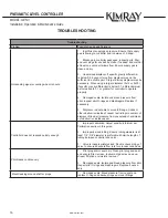
8
Start-up
WARNING:
Verify all pressure connections are tight before
pressurizing the system.
WARNING:
Never stand directly in front of or over a controller when
the system is pressurized.
WARNING:
Do not exceed Maximum Allowable Working Pressure or
maximum instrument supply pressure. Never loosen or
tighten any fitting while there is pressure on the line.
Pressurize the system. If any leaks are detected, bleed
off pressure and address. Failure to take the controller
out of service immediately may create a hazardous
condition.
Calibration
Calibrate the controller’s set point with no liquid on the
displacer.
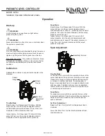
Supply
Gauge
Output
Gauge
Set Point
Adjustment
Knob
Throttle Mode:
Direct Acting - Fail Closed (aka PO) Valve: With the
output at 0 psi, turn the set point adjustment knob
counterclockwise to produce about 10 psi. Next, turn
clockwise until the output reaches 0 psi.
Indirect Acting - Fail Open (aka PC) Valve: With the
output at 0 psi, turn the set point adjustment knob
clockwise until full output pressure is produced.
Operation
Snap Mode:
Direct Acting - Fail Closed (aka PO) valve: With the
output at 0 psi, turn the set point adjustment knob
counterclockwise to “snap on”, producing the full output
pressure. Then turn the knob clockwise until the output
pressure returns to 0 psi.
Indirect Acting - Fail Open (aka PC) valve: At full
output pressure, turn the set point adjustment knob
counterclockwise to “snap off” the output pressure to
0 psi. Then turn the knob clockwise until full output
pressure is reached.
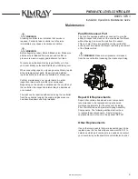
Span Adjustment
Sensitivity Fulcrum
Throttle Mode:
For throttle mode, start with the sensitivity fulcrum at the
center hashmark of the pilot lever. Note the current span.
If span is too large, move the sensitivity fulcrum inward
or outward to another hashmark. If resulting span is
larger, move sensitivity fulcrum in opposite direction and
note new span. If smaller, continue to move sensitivity
fulcrum further in the same direction until constant level
or minimum span is achieved.
Snap Mode:
For snap mode, start with the sensitivity fulcrum at the
innermost hashmark. This should yield the smallest span.
Adjust the fulcrum outward as need until the desired
span is achieved.
Set Point Adjustment
Raise Set Point: Turn the Set Point Adjustment Knob
clockwise
Lower Set Point: Turn the Set Point Adjustment Knob
counterclockwise
Содержание GEN 3
Страница 1: ...PNEUMATIC LEVEL CONTROLLER GEN 3...
Страница 20: ...2018 Kimray Inc RM 0021 Issued 3 21 Kimray com...