


36
Kice Industries, Inc.
FLT-M03-0002
012420
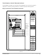
Appendix B Continued
Page 2 of 6
I&M No. V_6584_R19_sec1
©
ASCO Valve, Inc.
50 Hanover Road, Florham Park, New Jersey 07932 www.ascovalve.com
¹ = EF, EV data applies to Explosionproof coils only.
² = Some DC solenoid valves can be operated at maximum ambient
temperature of 55°C / 131°F with reduced pressure ratings. See
valve I&M for maximum operating pressure differential ratings.
³ = Steam Service Valves have a maximum ambient temperature of 55°
C/ 131°F.
CAUTION: To protect the solenoid valve or
operator, install a strainer or filter, suitable for the
service involved in the inlet side as close to the valve
or operator as possible. Clean periodically depending
on service conditions. See ASCO Series 8600 and 8601
for strainers.
ATTENTION : Afin de protéger l’électrovanne ou
l’actionneur, installer une crépine ou un filtre adapté
le plus proche possible en amont de l’électrovanne ou
de l’actionneur. Nettoyer périodiquement le filtre en
fonction des conditions d’utilisation. Se référer aux
séries 8600 et 8601 pour les crépines.
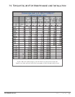
Temperature Limitations
For maximum solenoid ambient temperatures, refer to chart.
The temperature limitations listed, only indicate maximum
application temperatures for field wiring rated at 90
°
C. Check
catalog number prefix and watt rating on nameplate to determine
maximum ambient temperature. See valve installation and
maintenance instructions for maximum ambient and fluid
temperatures.
NOTE:
For steam service, refer to
Wiring
section,
Junction Box
for temperature rating of supply wires.
§ Minimum ambient temperature -40°F (-40°C).
Positioning
This solenoid is designed to perform properly when mounted in
any position. However, for optimum life and performance, the
solenoid should be mounted vertically and upright to reduce the
possibility of foreign matter accumulating in the solenoid base
sub-assembly area.
Wiring
Wiring must comply with local codes and the National Electrical
Code. All solenoids supplied with lead wires are provided with a
grounding wire which is green or green with yellow stripes and
a 1/2˝ conduit connection. To facilitate wiring, the solenoid may
be rotated 360
°
. For explosionproof solenoid version, the conduit
lead wires are factory sealed for use in hazardous locations.
CAUTION: Cryogenic Applications - Solenoid lead
wire insulation should not be subjected to cryogenic
temperatures. Adequate lead wire protection and
routing must be provided.
ATTENTION: Application cryogénique. Les
câbles électriques ne doivent pas être soumis à des
températures cryogéniques. Une protection adequate
des cables électriques doit être fournie.
Additional Wiring Instructions For Optional Features:
•
Open-Frame solenoid with 1/4˝ spade terminals.
For solenoids supplied with screw terminal connections use #12-
18 AWG stranded copper wire rated at 90
°
C or greater. Torque
terminal block screws to 10±2 in-lbs [1,0±1,2 Nm]. A tapped hole
is provided in the solenoid for grounding, use a #10-32 machine
screw. Torque grounding screw to 15-20 in-lbs [1,7-2,3 Nm]. On
solenoids with screw terminals, the socket head screw holding the
terminal block to the solenoid is the grounding screw. Torque the
screw to 15-20 in-lbs [1,7-2,3 Nm] with a 5/32˝ hex key wrench.
•
Junction Box
The junction box is used with spade or screw terminal solenoids
only and is provided with a grounding screw and a 1/2˝ conduit
connection. Connect #12-18 AWG standard copper wire only to
the screw terminals. Within the junction box use field wire that
is rated 90
°
C or greater for connections. For steam service use
105
°
C rated wire up to 50 psi or use 125
°
C rated wire above
50 psi. After electrical hookup, replace cover gasket, cover, and
screws. Tighten screws evenly in a crisscross manner
.
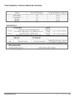
Temperature Limitations for Series 8003H, 8007H and 8202H
solenoids
Watt Ratings
Maximum Ambient
Temperature
Prefix ¹
Coil
Class
AC
DC
60 Hz
50 Hz
°C
°F
EF, EV
FT
10.1
10.1
-
52
125
EF, EV
FB
17.1
17.1
-
FT
10.1
10.1
-
55
131
FB
17.1
17.1
-
HT
-
-
11.6
40 ²
104 ²
HF
-
-
15.6
HB
-
-
22.6
EF, EV
HT
-
-
11.6
EF, EV
HF
-
-
15.6
EF, EV
HB
-
-
22.6
HT
10.1
10.1
-
60 ³
140 ³
HB
17.1
17.1
-
EF, EV
HT
10.1
10.1
-
EF, EV
HB
17.1
17.1
-
EF, EV
HC
-
-
24.6
Multipin Connector
Connector Type
Mating Connector
Application
VT / VB
4-Pin, M12, Female, Single Keyway
DC
4-Pin, M12, Female, Dual Reverse
Keyway
AC
ZT / ZB
3-Pin, Mini, Female, Single Keyway
AC / DC
•
DIN Plug Connector Kit No. K236034
1.
The open
-
frame solenoid is provided with DIN terminals
to accommodate the plug connector kit.
2.
Remove center screw from plug connector. Using a small
screwdriver, pry terminal block from connector cover.
3.
Use #12
-
18 AWG stranded copper wire rated at 90
°
C
or greater for connections. Strip wire leads back
approximately 1/4˝ for installation in socket terminals.
The use of wire
-
end sleeves is also recommended for
these socket terminals. Maximum length of wire
-
end
sleeves to be approximately 1/4˝. Tinning of the ends of
the lead wires is not recommended.
4.
Thread wire through gland nut, gland gasket, washer and
connector cover.
NOTE:
Connector housing may be rotated in 90
°
increments
from position shown for alternate positioning of cable entry.
Temperature Limitations For Series 8003G, 8007G or 8202G
Watt
Rating
Catalog
Number Coil Prefix
Class of
Insulation
Maximum §
Ambient Temp.
10.1 & 17.1
None, FB, KF, KP,
SC, SD, SF, SP, VT, VB,
ZT & ZB
F
125°F (52°C)
10.1, 17.1 &
24.6
HB, HT, KB, KH, SS, ST,
SU, HC
H
140°F (60°C)
11.6 & 22.6
None, FB, KF, KP,
SC, SD, SF, SP, VT, VB,
ZT & ZB
F
104°F (40°C)
11.6 & 22.6
HP, HT, KB, KH,
SS, ST, SU & SV
H
104°F (40°C)
15.6
None, KB, SS, SV
H
104°F (40°C)