


14
Kice Industries, Inc.
FLT-M03-0002
012420
WARNING:
High voltage and rotating parts can cause serious or fatal injury. Only qualified
personnel should perform installation, operation and maintenance of electrical machinery.
Make sure that any electric motor and the frame of the filter is effectively grounded in
accordance with OSHA standards, the National Electrical Code and local codes.
7. Connect the medium pressure air supply (10-15 psig) to the filter air tank, utilizing the pressure
regulator, filter and valve(s), if required.
8. The Kice Pneu-Jet filter controller is normally mounted adjacent to the Kice Pneu-Jet filter housing
access door. However, it can be mounted in any convenient location. Orientation of the controller
does not affect its performance.
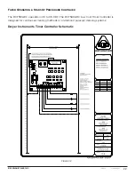
9. Electrical conduit and junction tees (one at each Kice Pneu-Jet solenoid valve) are furnished with
each filter. On filters with one air tank, the electrical manifold is pre-wired from the solenoids directly
to the control box. On filters with two or more air tanks, each tank has an electrical manifold that is
pre-wired from the solenoids to a junction box. Each air tank has its own junction box. A local
electrician must run a conduit from the control box to each junction box on the filter. Wiring from the
controller to the junction box terminals should be #18 gauge. One wire from each solenoid is
connected to the corresponding terminal on the terminal strip. The second wire for each solenoid
is connected to the common/neutral lead. For ease in assembly, a white wire should be used for
the common/neutral lead. Wires of any color other than white or green can be used for the hot lines
(numbering each end may be helpful).
NOTICE:
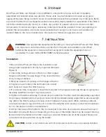
Reference Figure 14 in the Operating Logic section for example wiring diagram.
10. The sequence controller is not dependent on the successful firing of the Kice Pneu-Jet blast
valve to advance to the next valve in sequence. If, for any reason, a Kice Pneu-Jet blast valve does
not fire, the controller will continue to time out the “off” time and activate the next valve in
sequence.
11. Some systems will have a fan and airlock valve to be connected. Verify that the fan and airlock
rotation direction is correct as marked.
12. Test run the filter. If any unusual noises occur, disconnect and lock out the power. Check the fan,
airlock valve and screw conveyor, if furnished.
13. Reassemble any doors or covers removed during installation.
Installation Continued