KICE Pneu-Jet Filter Скачать руководство пользователя страница 27

27

Kice Industries, Inc.

FLT-M03-0002

012420

Daily Filter Inspection

1. Check and note pressure differential across the filter bags. It is recommended that filter bags be 
replaced when they can no longer be cleaned to 6.0” 

WC

 differential pressure. Normal pressure 

differential for new filters should read around 0.5”w.c. or as low as 0.1-0.2”w.c. 
2. Check the electronic controls to make sure all valves are operating.

General Valve Maintenance

Cleaning: Periodic cleaning of all valves is desirable. The time between cleaning will vary, depending
upon the condition of the plant air supply. In general, sluggish valve operation or excessive leakage or
noise will indicate that cleaning is required.

Preventative Maintenance: Periodic inspection of internal valve parts for damage or excessive wear is
recommended. Thoroughly clean all parts. Replace any parts that are worn or damaged.

Causes of Improper Operation: 

1. Incorrect Pressure: Check valve pressure. Pressure to valve must be within 2-15 psig.
2. Excessive leakage: Disassemble valves and clean all parts. Replace parts that are worn or
damaged with a complete Spare Parts Kit (see Figure 16).
3. Failure to Open or Close:

a. If the blast valve stays open, the bleed hole in the diaphragm may be clogged. If the blast valve
stays closed, the diaphragm may be torn. Disassemble the valve and clean or replace the
diaphragm assembly.
b. Failure of the solenoid operated pilot valve can also cause the blast valve to stay closed or 
open. Inspect the solenoid operated pilot valve for proper operation.

WARNING:

 Depressurize the valve and bleed air from the air tank before making repairs. To

do so, it is only necessary to activate the solenoid on the pilot valve or remove one pilot
valve from one blast valve.

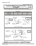
Kice Pneu-Jet Blast Valve 

Description:

 The Kice Pneu-Jet blast valve is a 2 way, NC, diaphragm type air valve designed for 

remote pilot operation. This valve has an aluminum body with 3” pipe port connections and 3” orifice 
diameter (see Figure 16).

NOTICE: 

Reference ASCO Valves installation and maintenance instructions in 

Appendix A

.

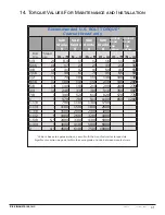
9. Filter Maintenance and Service

Содержание Pneu-Jet Filter

Страница 1: ...1 Kice InDustries Inc FLT M03 0002 012420 Operators Manual Pneu Jet Filter Skilled Air for Industry Operators Manual Pneu Jet Filter Pneu Jet Filter Skilled Air for Industry...

Страница 2: ...from the date of shipment Company agrees to repair or replace at its option any parts found to be defective in the opinion of the Company Company is not liable for any costs in connection with the re...

Страница 3: ...tion 4 3 General Information 5 4 Safety Precautions 9 5 Delivery Inspection and Installation Preparation 12 6 Storage 13 7 Installation 13 8 Filter Operation and Start Up Procedure 19 9 Filter Mainten...

Страница 4: ...or additional information application assistance or special service please contact us by phone at 316 744 7151 or email at sales kice com We ll need to know the MODEL and SERIAL NUMBER of your Kice Pn...

Страница 5: ...erms disconnect and lockout or lockout tagout as used in this manual means that power to the Kice Pneu Jet filter has been disconnected through the use of a padlockable manual power cutoff or power lo...

Страница 6: ...ts contact the Customer Service Department or Quick Ship Department Kice Industries Inc 5500 Mill Heights Drive Wichita Kansas 67219 2358 Toll Free 877 289 5423 Main Phone 316 744 7151 Fax 316 744 735...

Страница 7: ...chased items such as speed reducers motors and positive pressure pumps are covered by the manufacturer s warranty If there is a problem with a purchased item check with the local supplier or service r...

Страница 8: ...res The following publications provide valuable information on fire and explosion protection and can be helpful to insure your facility is properly equipped NFPA 652 Standard on the Fundamentals of Co...

Страница 9: ...r personal safety When you see this symbol be alert Your personal safety or the safety of others may be affected Follow the instructions in the safety message Safety Decals The Kice Pneu Jet filter de...

Страница 10: ...s all moving parts are completely enclosed and all guards grates and maintenance panels are in place and securely fastened All protective covers guards grates maintenance panels switches and warning d...

Страница 11: ...omplete required Kice Pneu Jet filter service Never stand under any kind of hoists or lifting mechanisms whether or not it is loaded or in operation Never stand under or near a Kice Pneu Jet filter or...

Страница 12: ...filter is still secured to freight platform Slab Mounted Units A qualified engineer should design the foundation and or footings for the filter The slab should be extended to support accessory equipme...

Страница 13: ...ound each hole and mount the filter housing 4 If an airlock valve is required it should be mounted to the hopper discharge flange or sight glass assembly Additional support may be required 5 Tighten a...

Страница 14: ...ch air tank has its own junction box A local electrician must run a conduit from the control box to each junction box on the filter Wiring from the controller to the junction box terminals should be 1...

Страница 15: ...form make sure the tabs on both sides of the cleaning platform are on the outside of the door frame Check to make sure the cleaning platform is level and secure The platform should not rest against or...

Страница 16: ...stem NOTICE Kice Industries Inc will always supply internal safety grating in the bottom of the filter housing if it is to be mounted onto a storage bin to prevent personnel bags and cages from droppi...

Страница 17: ...igure 7 Installation Continued Figure 7 2 Check the filter bag for proper length The filter bag should be only 2 longer than the bag retainer cage 3 Tuck the overextended portion of the filter media i...

Страница 18: ...the assembly from slipping off see Figure 11 7 Tighten the clamp with either a screwdriver a nut runner with a 5 16 socket or a ratchet with an extension which will help facilitate the installation It...

Страница 19: ...pressurized air through the manifold into the top of each bag in that row This pulse of air causes the dust particles collected externally on the filter media to be dislodged and fall into the hopper...

Страница 20: ...es the pressure equalizes allowing the diaphragm to close As the pulse of air is fired through the manifold and down the tubes located above the filter bag the pulse creates a shock effect that dislod...

Страница 21: ...ller will activate the outputs sequentially whenever the pressure switch contacts are closed When the pressure switch contacts open the output sequencing stops Reclosing of the contacts will cause the...

Страница 22: ...ration Start Up Procedure Continued The DCT510ADC operates on 10 to 35 VDC The DCT500ADC Low Cost Timer Controller is designed for continuous cleaning methods or on demand pulse jet cleaning systems D...

Страница 23: ...Milliseconds Opera ng Voltage 120 10 VAC 50 60 Hz O Time Adjustable from 1 to 180 Seconds DCT1022DC Adjustable from 1 to 225 Seconds Op onal Voltage 220 10 VAC 50 60 Hz Output Protection Type 10 30 V...

Страница 24: ...vate followed by an independently timed off period Each time sequence is infinitely adjustable within the stated time range Following the number 1 on and off time the number 2 on and off time will be...

Страница 25: ...x 10 x 5 11 20 DNC T2032 A10 32 14 x 12 x 6 17 32 1994 to 2008 Specifications Time Delay Input On Time Adjustable from 50 to 500 Milliseconds Opera ng Voltage 120 10 VAC 50 60 Hz O Time Adjustable fr...

Страница 26: ...shipment and to allow a short run in time for the electronics 6 Set the controller off time adjustment to a longer time span by rotating the dial clockwise until you cannot turn the dial any further W...

Страница 27: ...ssure to valve must be within 2 15 psig 2 Excessive leakage Disassemble valves and clean all parts Replace parts that are worn or damaged with a complete Spare Parts Kit see Figure 16 3 Failure to Ope...

Страница 28: ...ure the air tank is at atmospheric pressure 1 The solenoid operated pilot valve is mounted to the main valve bonnet with four screws Remove bonnet screws valve bonnet diaphragm spring and diaphragm as...

Страница 29: ...29 Kice Industries Inc FLT M03 0002 012420 Filter Maintenance and Service Continued Figure 16...

Страница 30: ...en solenoid with lead wires and conduit connection is designed to meet Enclosure Types 4 and 4X Watertight The black solenoid designated by catalog number prefix EF is designed to meet Enclosure Types...

Страница 31: ...e dust may buildup to the point that the filter media needs to be removed for cleaning This condition may be corrected by running the cleaning cycle without the dusty air flowing through the filter me...

Страница 32: ...or leaks a Check the Pneu Jet blast valves for leaks b Check to see if any of the Pneu Jet blast valves are stuck open and bleeding the tank air straight to the filter The electric operated 2 way pilo...

Страница 33: ...rce 4 DO NOT mount the control in a high transient voltage area without an isolation transformer 5 DO NOT leave the control box door open 6 DO NOT allow a local repair shop to repair the controller Fo...

Страница 34: ...ld Kit number stamped on the valve nameplate When Ordering Coils for ASCO valves order the number stamped on your coil If the number of the kit or the coil is not visible order by indicating the numbe...

Страница 35: ...tion Box This junction box construction meets Enclosure Types 2 3 3S 4 and 4X Only solenoids with 1 4 spade or screw terminals may have a junction box The junction box provides a 1 2 conduit connectio...

Страница 36: ...uctions For Optional Features Open Frame solenoid with 1 4 spade terminals For solenoids supplied with screw terminal connections use 12 18 AWG stranded copper wire rated at 90 C or greater Torque ter...

Страница 37: ...nal valve parts for damage or excessive wear is recommended Thoroughly clean all parts Replace any worn or damaged parts Causes of Improper Operation Faulty Control Circuit Check the electrical system...

Страница 38: ...g Series 8202G without adapter Torque Chart Part Name Torque Value in Inch Pounds Torque Value in Newton Meters solenoid base sub assembly 175 25 19 8 2 8 pipe adapter 90 maximum 10 2 maximum adapter...

Страница 39: ...inal block see note junction box gasket junction box with 1 2Iconduit connection and grounding terminal cover screw cover cover gasket grounding screw and cup washer gasket DIN terminal adapter See to...

Страница 40: ...nut gland gasket washer center screw Figure 6 DIN plug connector kit No K236034 optional feature See torque chart above Page 6 of 6 I M No V_6584_R19_sec2 ASCO Valve Inc 50 Hanover Road Florham Park...

Страница 41: ...8 Socket head Socket head cap screw cap screw Bolt Thread Dia Size 1 4 20 8 4 11 12 16 11 15 5 16 18 17 24 25 33 23 31 3 8 16 31 42 44 59 41 55 7 16 14 49 67 70 95 65 59 1 2 13 74 100 110 140 100 140...

Страница 42: ...42 Kice Industries Inc FLT M03 0002 012420 2016 Kice Industries Inc 5500 N Mill Heights Dr Wichita KS 67219 2358 P 316 744 7151 F 316 744 7355 sales kice com kice com...

Отзывы: