Installation Note N5247-90116 17
Description of the Upgrade
Installation Procedure for the Upgrade
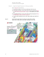
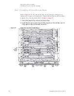
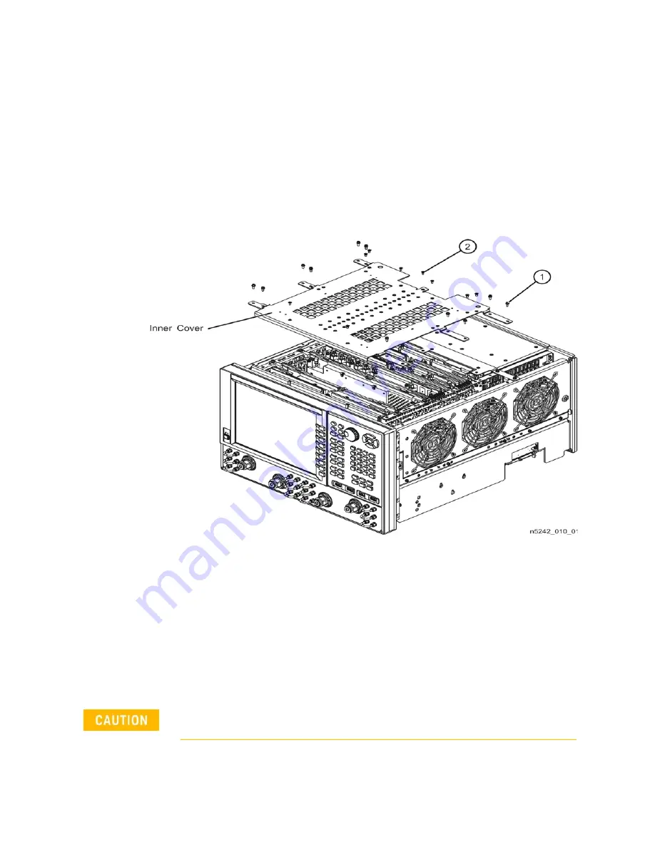
Step 3. Remove the Inner Cover
Refer to
for this step of the procedure.
1. With a T-10 TORX driver, remove the 12 pan head screws (item
①
).
2. With a T-10 TORX driver, remove the 9 flat head screws (item
➁
).
3. Lift off the cover.
Figure 2
Inner Cover Removal
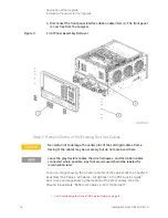
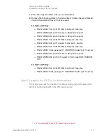
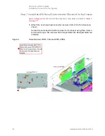
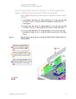
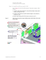
Step 4. Remove the Front Panel Assembly
for this step of the procedure.
1. With a 5/16-in wrench, remove all front panel jumpers (item
①
).
2. With a T-10 TORX driver, remove the screws (item
➁
) from the sides of the
frame.
3. Slide the front panel over the test port connectors.
Before removing the front panel from the analyzer, lift and support the
front of the analyzer chassis.
Содержание N5247-60116
Страница 3: ...3 ...
Страница 4: ...4 ...
Страница 44: ...44 Installation Note N5247 90116 Description of the Upgrade Installation Procedure for the Upgrade ...
Страница 45: ...Installation Note Xxxxx xxxxx 3 ...


