background image

28 


or


Wait a few seconds for the system to return to Normal Operating Mode. Thermostat presets and schedule will be 
executed automatically. 


IMPORTANT NOTES: 

 
A)  

In both “AUTO” and “MANU”al modes: 

In order to ensure proper operation of 

COOLING 

and 

HEATING 

Auto 

Switch-Over 

function, the presets for 

SUNDAY 

Events 

14 

and 

15 MUST 

be programmed and stored.  Programming of those events 

must 

be performed in “AUTO” mode. 

-  

COOLING switch-over 

temperature preset (SUNDAY event 15) is the temperature 

ABOVE 

which the Cooling relay contact 

will be allowed to close but only when 

Target Temperature is lower 

than temperature sensed by the probe. 

-  

HEATING switch-over 

temperature preset (SUNDAY event 14) is the temperature 

BELOW 

which the Heating relay contact 

will be allowed to close but only when 

Target Temperature is higher 

than temperature sensed by the probe. 


B)  

Preset Temperature for “MANU”al mode: 

Target Temperature for “MANU”al mode is stored in 

SUNDAY event 13 

. It may be preset in either “MANU”al or “AUTO” 

mode. 
“MANU”al mode is also using 

COOLING 

and 

HEATING 

Auto 

Switch-Over 

function, as preset for 

SUNDAY 

Evens 

14 

and 

15 .

Programming of those events 

must 

be performed in “AUTO” mode. 

 
C)  

The order in which the thermostat is searching for active events is from event “00“ thru event “15“. The search is performed 

at 00 seconds of each minute of real time. First encountered active event shall be executed and further search shall be 
aborted until next minute of real time clock reading.  Therefore, if more than one event for the day has the same time as any 
other, only the younger (in order) event number shall be executed. This may have application in deactivating unused events by 
setting them as identical to the highest used event number for the day. 
 

D)  

 When Power is Removed between event times, the thermostat will SEARCH BACK all active events that would have been 

valid after Power Returns subsequently.  This search is performed in REVERSED ORDER: from events 15 thru 00 of each 
day. The most recent, valid event will be executed. Therefore, care must be taken when programming the thermostat, so that 
unused events in each day either have -40F(C) set as Target Temperatures or the OLDEST event number for each day is 
copied into unused events for that day.


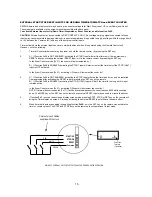
Both Internal Relays are operational in Programmable Thermostat modes. 

The relays’ contacts are brought out to back panel terminals as Normally Open. 
Contact designated as “

COOL

” will 

close 

when demand for cooling (Air-Conditioning) is detected. 

Contact designated as “

HEAT

” will 

close 

when demand for heating is detected. 

 
CONTACTS are enabled to change states only 

ONCE every 30 SECONDS


The drawing below shows how to connect External Probe and Heating and Air-Conditioning system to Internal Relays 
Contacts.


During Thermostat operation: 
1)  STEADY 

Light in upper-left corner of display indicates that “

HEAT” 

contact is closed.  

2)  BLINKING 

Light in upper-left corner of display indicates that “

COOL” 

contact is closed.  

These lights may be active 

ONLY 

when temperature is on display. 

To DISABLE PROGRAMMABLE THERMOSTAT operation: 

Terminals on back panel 

COOL  - 

 HEAT 

Ctr

l. Contacts 

PROBE 

TO HEATING SYSTEM 

CONTROL INPUTS 

TO AIR CONDITIONING 

SYSTEM 

CONTROL INPUTS 

Ext

ernal T

empera-

ture PROB

NORMALLY OPEN 

NORMALLY OPEN 

Use any type 

2-conductor cable to 

extend probe wiring 

3 Amp.

 , 240V  

max.


Содержание SELENA HY-4 Series

Страница 1: ...1 SELENA Multifunctional LED CLOCK series HY 4 and HY 6 Rev 18 KERA Technologies Inc E mail sales ledclocks com www ledclocks com ...

Страница 2: ...etup 13 External Inputs for Up Down Timer and Event Counter 16 Temperature Monitoring and Control 17 Internal Control Relay 18 Control Relay Wiring 18 Alarm Buzzer and Siren Operation 19 Min Max Temperature Memory 20 Master Slave System Clock Network 20 Multi zone Clock System 25 Minute Impulse Sync System 26 BCD Time Code Synchronization Slave Receiver 26 Master Slave Sync Signal Range Extender R...

Страница 3: ...External Timer and Counter inputs interface Daily Wake Up Alarm Clock Daily Programmable Timer 16 events day Daily Programmable Timer 1440 events day Weekly Programmable Timer 16 events day week Weekly Programmable Timer 2016 events week Digital Inside Thermometer Digital Outside Thermometer Min Max Temperature Memory High Low Temperature Alarm Digital Thermostat Programmable Heat Cool Thermostat ...

Страница 4: ...g display facing up or down SELENA may be used Stand Alone or in a Synchronized System as a Slave and or as the Master clock Alternately a number of clocks may be connected in a dedicated network to operate in a Multi Zone Clock System The on board control relay and buzzer in combination with the remote temperature probe may be used for the monitoring alarm and or control of programmable temperatu...

Страница 5: ...ER Connection NOTE Before installation determine voltage rating required for the particular clock model Make sure that all power is disconnected Please observe local electrical code requirements while installing power connections For models with power cord just plug it into available power outlet For models With Power Screw Terminal follow instructions 1 Locate the power screw terminal marked POWE...

Страница 6: ...y pressing MUTE key 5 times within appx 2 seconds 2 MUTE internal Alarm Buzzer TALK Initiate spoken announcement optional CLK Press it before operating other keys to put the Remote in the clock operation mode AP1 Appliance Type 1 remote operation mode not used in regular clock operation AP2 Appliance Type 2 remote operation mode not used in regular clock operation COUNT UP 1 Increments the count d...

Страница 7: ...stat mode initiates MANUal control HOLD 1 HALTS the display scrolling mode at the current display during regular operation 2 SAVES into memory the preset data for programmable event Timers and Thermostat NOTE that many keys may be operating only in certain conditions of display or functions selected Some keys may not be active depending upon the model and installed options FUNCTION SETUP Procedure...

Страница 8: ... Frequency for Power Line Carrier sync Also used for Protocol Format Selection bit 0 for ASCII Time Code or Protocol Selection bit 0 for Minute Impulse sync mode This function is also used when clock is configured for operation in Master Slave System Clock Network see section MASTER SLAVE SYSTEM CLOCK NETWORK Fn 12 Enable for Colon Blinking when sync detected for Power Line Carrier sync Also used ...

Страница 9: ...ER INPUT terminal if the External Counter Timer Inputs are enabled by Fn 36 or Clocked by the remote control UP and DOWN buttons if the external inputs are not enabled Counter Result count display is enabled by Fn 7 The Counter operates as UP COUNTER when the preset count is equal 000000 or as UP and DOWN COUNTER when the preset is different than 000000 but will not allow for clocking down from co...

Страница 10: ...the CURRENT TIME DISPLAY When selected this function will make the External Temperature see Fn 1 to be displayed longer than the Current Time Display see Fn 3 Each of possible seven display modes is setup by enabling any combination of functions Fn 0 to Fn 7 Fn 42 ENABLES automatic HALT of UP DOWN Timer during Power Failure This option can be used only if function Fn 42 is installed and Enabled Wh...

Страница 11: ... 59 300 BPS Communication speed selection for RS232 and RS485 If not selected then 9 600 BPS is used Fn 60 DAYLIGHT SAVING AUTOCHANGE CANADA USA and MEXICO Fn 61 RESERVED FOR SYSTEM CONFIGURATION DO NOT ALTER Fn 62 TOTAL DISABLE of REMOTE CONTROL TOTAL Lock out All subsequent COMMUNICATION with clock via the Remote Control may be disabled by setting this function to prevent unauthorized operation ...

Страница 12: ...thin several seconds and the clock will resume regular operation Use NXT key to move the cursor when needed 1 Press SELECT NXT key to initiate Time Preset Mode 2 Using SELECT FUN key scroll to display screen with month and year and set the current data 3 Using SELECT FUN key scroll to display screen with date and month and set the current date 4 Using SELECT FUN key scroll to display screen with d...

Страница 13: ...t Alarm Time is satisfactory wait for few seconds for the display to return to regular operation Slow flashing of the lower right decimal point will indicate that alarm is activated TO CANCEL Wake Up Alarm press STOP key at any time during normal clock operation The lower right decimal point will extinguish in response IMPORTANT Whenever function Fn 39 is enabled the WAKE UP ALARM will be automati...

Страница 14: ...emain in the Timer Display mode to continue the Up Down Timer operation During Count Down a DOT in the lower right corner of the display will be rapidly flashing if the display is in Real Time Display mode If it is in Timer Display mode the Colon Dots will flash rapidly instead In the Counter mode the colon is extinguished This is an indication that TIMER is operating In the HALT timer mode the co...

Страница 15: ...activating the START input will start or restart the timer only if the STOP HALT input is NOT activated In the Event Counter mode Fn31 activating UP input will increment the count by 1 3 A If Function Fn58 is NOT ENABLED activating the STOP input will stop the timer and it may only be restarted from beginning after activating the RESET input or pressing the SET key on the remote B If Function Fn58...

Страница 16: ... wiring of the internal probe rather than a probe already installed in Internal Housing All operation of such probe remains unaffected but care should be taken to avoid unwanted transfer of the clock s or other equipment heat cold to the probe in order to prevent incorrect readings Temperature Display and Control activation 1 To assure that External Temperature is displayed ALL the time enable Fun...

Страница 17: ...Only when power cord installed B Relay Only when screw terminal for power installed C Relay and Internal DC Power Source 2 Attach the load wiring to the terminal and secure it with terminal screws NOTE Wiring should be of sufficient gauge to carry the load current and insulation should be appropriate for load voltage Remember to provide adequate fuse protection 3 Affix wiring cables to the tie wra...

Страница 18: ...er Expiry ALARM or when Timer Counter is not running It will be switched ON while Timer Counter is running 2 When Fn 18 is Disabled Internal relay will be switched ON in response to Count Down Timer Counter Expiry ALARM and will remain NORMALLY switched OFF in all other conditions In both of the above modes activate SET key to Reset the Internal Relay to OFF state and Reset the Timer Counter Contr...

Страница 19: ... wire and Reverse Polarity 1 Minute and 1 2 Minute Impulse 4 RS 232 or RS 485 compatible computer communication network 5 BCD Time Code Simplex compatible for 50 and 60 Hz clock speed System with Power Line Carrier Synchronizing signal Fn 23 enabled Large System Clock installations may be synchronized by injecting a strong low frequency signal into the power line at certain times of the day The Sl...

Страница 20: ...e Master In this configuration the Slave will not be able to perform any other display functions except when it is put in a programming mode via the Remote Control ASCII TIME CODE protocol To select the Format for the ASCII Time Code protocol Enable the function Fn46 and set the following functions as required Fn13 Fn12 Fn11 Format 0 0 0 0 SELENA may be set as a Slave or as a Master Format 1 0 0 1...

Страница 21: ...HE SAME NETWORK OR A COLLISION WILL OCCUR A Twisted Pair cable must be connected IN PARALLEL to all clocks in the system Additional clocks may be added at any time and or taken away from the system either by Selecting Deselecting the appropriate Sync Control functions Fn 32 33 and 34 as needed or physically Clocks that are not enabled as slaves may continue to operate as stand alone Normally up to...

Страница 22: ...r cable must be connected IN PARALLEL to all clocks in the system Additional clocks may be added at any time and or taken away from the system either by Selecting Deselecting the appropriate Sync Control functions Fn 33 and 34 or physically To keep a Slave clock time synchronized with the Master function Fn 34 must be enabled Function Fn33 is only used in Special Applications for display repeater ...

Страница 23: ...to 30 VDC presented at appropriate inputs The current requirements are very low and are equivalent to an Input Resistance of 10 Kohm The input is electrically isolated from all internal electronics via high insulation optocoupler that can withstand high voltage differences of over 1 500V This Sync option can receive BCD Time Code at either 50Hz or 60Hz clock speed and it detects the correct clock ...

Страница 24: ...24 UP TO 64 SLAVES Or Optional up to 400 slaves TO OTHER SLAVES IN THE NETWORK OPTIONAL when required CLOCK WITH OPTO REPEATER PC COMPUTER With installed PC2KERA driver S W MASTER CLOCK SELENA or Other ...

Страница 25: ...up as close as possible to the master seconds After the first minute of operation the slaves and the master will go in synch NOTE To prevent an unauthorized access tot the clock setup the function Fn 62 may be enabled ALL COMMUNICATION with the clock via remote control is then DISABLED To regain the remote control access remove the power momentarily and disable Fn 62 within 33 seconds Similarly th...

Страница 26: ...et required time of the event To move the cursor press NXT key 6 When satisfied with the preset time and duration press HOLD key to store the data in memory MAKE SURE that this is done WHILE either duration or Alarm Hours Minutes is on display If it is not done so the OLD data shall be restored in memory 7 Display will flash text Strd momentarily to indicate that the Alarm data has been stored in ...

Страница 27: ...rature will follow NOTE Pressing STRT button will invoke AUTO mode of operation 2 For 2016 events week thermostat go directly to Step 3 A If in AUTO mode the event number will flash rapidly to indicate that it is active for selection Use UP and DN keys to select event number for that day B If in MANU al mode preset temperature will flash rapidly to indicate that it is active for selection Use UP a...

Страница 28: ...ounger in order event number shall be executed This may have application in deactivating unused events by setting them as identical to the highest used event number for the day D When Power is Removed between event times the thermostat will SEARCH BACK all active events that would have been valid after Power Returns subsequently This search is performed in REVERSED ORDER from events 15 thru 00 of ...

Страница 29: ...ted and with what presets To do that press SET key on the remote at any time The most recently executed event will be shown Use NXT key to scroll through day temperature and hrs minute for that event NOTE that at this point the system will also accept new settings for this and other events IMPORTANT NOTE Due to location of Internal probe near the clock s enclosure its temperature may be slightly a...

Страница 30: ... Mode 8 1 1 1 0 2007 OCT 12 Mode 9 0 0 0 1 TEMP 25 3 C or 77 5 F also see Fn 0 and Fn 1 Mode 10 1 0 0 1 XX XX XX timer or counter also see Fn 31 Mode 11 1 0 0 1 DAY 245 Julian day of the year Mode 12 0 1 0 1 TIME ZONE Customer TEXT DISPLAY NOTE that if Function Fn 71 is enabled the Text display will remain blank at all times In order to make the Text display show either IN or OUT temperature or ha...

Страница 31: ...31 ...

Страница 32: ...32 ...

Страница 33: ...vents per week Event duration programmability Option 1 0 to 59 seconds in 1 sec steps Timers resolution 1 sec Standard 1 100 sec Optional Event counter range presettable 0 to 9999 99 counts up or down Counter input spec s Dry contact min pulsewidth 2 msec max pulse frequency 250Hz Internal Temperature probe Thermistor 1 50kohm 40C 40F to 140C 284F External Temperature probe Remotely wired up to 50...

Страница 34: ...adiate radio frequency energy and if not installed and used in accordance with the instruction manual may cause interference to radio communications It has been tested and found to comply with the limits for a Class A computing device pursuant to subpart J of Part 15 of FCC rules which are designed to provide reasonable protection against such interference when operated in a commercial environment...

Страница 35: ...D WARRANTY For a period of one year from the date of delivery 90 days for the keyboard the Manufacturer warrants to the original user that the display system shall be free from defects in materials and workmanship This warranty shall be void if the unit is altered or modified in any way by the user This warranty shall not apply to external parts including the cabinet and repairs or replacements ca...

Отзывы: