TKR-740
17
*3 TD ; TX Data input-transmit signalling (QT / DQT / LTR)
input. (Impedance 600
Ω
)
TA ; TX Audio input-transmit audio input.
(Impedance 600
Ω
)
RD ; Receiver detector output non-squelched, non-de-
emphasized detector audio output ( 80mVrms/4.7k
Ω
)
RA ; Receiver Audio output-with de-emphasis, filtering
and squelched, line level only (not for driving a
speaker). ( 400mVrms/ 4.7 k
Ω
)
PTT ; Press-to-Talk-external transmit key line.
TXG ; TX Ground-common ground.
1.4. REM T I/ O jack
Connector
No.
Terminal Name
Description
I/ O
Level
1
Remote RA (RX Audio output)
Audio output, line level
*1
O
400mVrms
2
Remote TA (TX Audio input)
Audio input, line level
*1
I
140mVrms
3
Remote PTT
Remote PTT input (Active-Low)
*1
I
0 or 5V
4
EXT MON
External Monitor input (Active-Low)
I
0 or 5V
5
GND
Ground
6
AUX I/O 1
External Ch 1 or programmable Function
*2 *3
I/O
0 or 5V
7
AUX I/O 2
External Ch 2 or programmable Function
*2 *3
I/O
0 or 5V
8
AUX I/O 3
External Ch 3 or programmable Function
*2 *3
I/O
0 or 5V
9
AUX I/O 4
External Ch 4 or programmable Function
*2 *3
I/O
0 or 5V
10
AUX I/O 5
External Ch 5 or programmable Function
*2 *3
I/O
0 or 5V
11
AUX I/O 6
Programmable Function
*2 *4
I/O
0 or 5V
12
AUX I/O 7
Programmable Function
*2 *4
I/O
0 or 5V
Notes:
*1 Remote RA ; Receiver Audio output with de-emphasis to
Remote Terminal.( 400mVrms/ 4.7 k
Ω
Load)
Remote TA ; Transmit audio signal input from Remote
terminal.(Impedance 600
Ω
)
Remote PTT ; Press-to-Talk for Remote Terminal transmit
key.
*2 AUX I/O 1-5 can be programmed for AUX Input, AUX
Output or (BCD) Channel Select.
AUX I/O 6-7 can be programmed for either AUX Input or
AUX Output.
*3 AUX I/O 1-5: Provides 1 of 32 channel selection via 5 bit
Binary Coded Decimal (BCD) on REMT I/O connector.
RE
M
T
I
/O
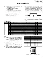
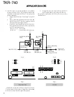
*4 The output logic level of all AUX O terminals (Section 1.3,
1.4), including any AUX I/O programmed as
“
AUX Output
”
with the KGP-47D may be selected as either Active-High
or Active-Low. Note: If Active-Low is selected in KGP-
47D, the AUX Output port will be driven temporarily High
for about 500ms immediately after a forced reset or when
power is first applied. External equipment must have
appropriate de- bounce.
Select channel
No. 10 9 8 7 6 pin
1
1 1 1 1 1
2
1 1 1 1 0
3
1 1 1 0 1
4
1 1 1 0 0
...
...
29
0 0 0 1 1
30
0 0 0 1 0
31
0 0 0 0 1
32
0 0 0 0 0
APPLICATION NOTE
1
2
3
4
5
6
7
8
9
10
11
12
REM T I/ O jack (View ed from Back Panel)
Power ON or Reset
For about 500ms,
the AUX O is driven High
AUX O
*5 EXT MON is the same as EXT MON on the REMT I/O (Section
1.4).
Содержание TKR-740
Страница 97: ...TKR 740 TKR 740 BLOCKDIAGRAM 121 122 ...
Страница 99: ...TKR 740 TKR 740 INTERCONNECTION DIAGRAM 125 126 ...
Страница 101: ...MEMO 129 ...

