External I/Os MultiSensor-LAN
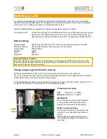
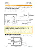
Examples of external circuits of the MultiSensor-LAN. Shows the internal 8-pin terminal of the the
MultiSensor. The Internal circuit of inputs and outputs is shown schematically for better understanding. The
logic of the alarm inputs can be rotated in the PC software.
Example 1: Wired connection with power supply via internal terminal.
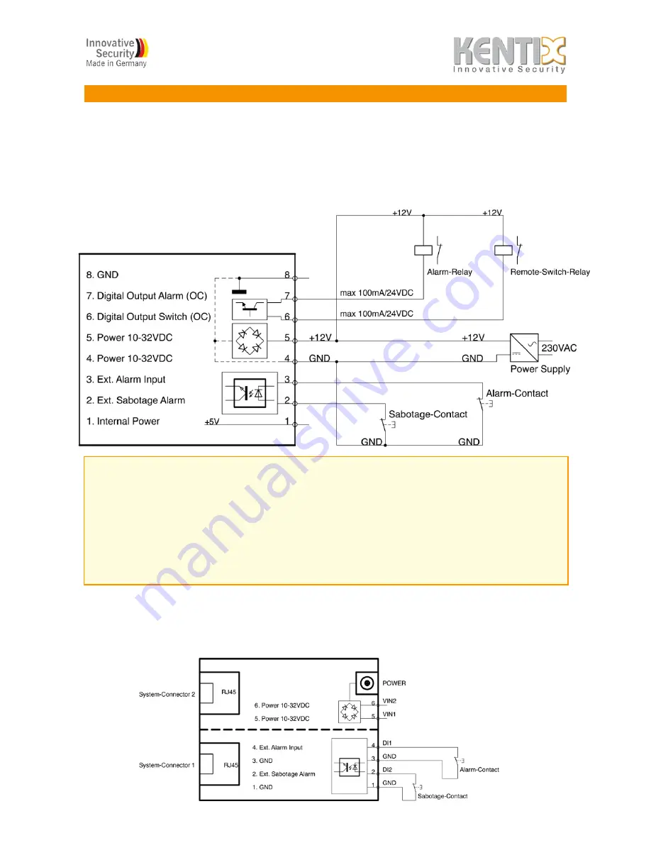
Example 2: Connection via PowerAdapter (KIO1)
With the Power Adapter (KIO1), two devices (AlarmManager, MultiSensor) are supplied with power. The alarm inputs of
the device are only on "System connector 1" of the terminal connection of the KIO1 adapter available.
Page 12
!
(09-2012, subject to change)
!
www.kentix.de
IMPORTANT!
The switching outputs 6/7 are open collector transistor outputs and the maximum load is 100mA. For plug
´n play use of the outputs you can choose the KENTIX modules of following types: KIO1, KIO2
The switching output 6 can only be activated via the SMS remote function.
The switching output 7 is automatically switched by an ALARM1 or ALARM 2 trigger.
The alarm inputs 2/3 can be directly connected with dry contacts.
If you are using the system jack for power supply you can switch the alarm inputs 6/7 direct to the pin 8


