Kendrion Binder Magnete GmbH
Operating Instructions 76 ..P..B00
Last updated: 30 Dec. 2009
Page 19
Deep groove ball bearing (18):
When performing maintenance and repair work, check that the deep groove ball bearing (18) rotates
smoothly. If the bearing (18) needs to be replaced, proceed as described above under "Brake removal from
the machine (e.g. motor)" and "Opening the solenoid housing (1.1)". After having removed the friction disc
(5), remove the circlips (14 and 15). Push the hub (17) and deep groove ball bearing (18) out of the solenoid
housing (1.1) and remove the bearing (18) from the hub (17). Before reassembling the spring-applied brake,
all components (except for the friction disc (5)) must be cleaned with grease-free cleaners. In order to
assemble the individual components, proceed in reverse order of removal. When fine adjusting the M
2
rated
torque, make sure that the machine screws (32) project from the flange (3) by the length x
nom
(approximate
value – see Table 17/1) marked on the flange (3). The self-locking nuts (31) (to ISO 10511-04-A2F; 140°C)
must be replaced before adjusting the screws.
Attention!
When the spring-applied single-disc brake is mounted to the machine, it is crucial that the fixing screws (10)
be tightened applying the M
A
tightening torque specified in Table 7/1. The machine screws (20) on the cover
(7) and the machine screws (22) must be tightened to the M
A
torque specified in Table 13/1. The O-ring (24),
spring washer (21 and 28) and flat seal (9) must be installed as shown in Fig. 6/1.
Attention!
Depending on its operating condition, it may no longer be possible to release the spring-applied single-disc
brake when the maximum air gap s
max
(see "Technical specifications") has been exceeded. In this case, the
braking effect cannot be neutralised.
Warning!
If a hand release lever (29) is fitted to the brake and the maximum air gap s
max
(see "Technical
specifications") has been exceeded (especially in case of a reduced M
2
rated torque), the hand release lever
(29) may limit the axial movement of the armature (2). This would cause the torque to be reduced down to
zero. Whenever carrying out maintenance work, check the degree of wear of the friction disc (5) and the air
gap 's' and replace the friction disc (5) well before the maximum air gap s
max
(see "Technical specifications")
is reached.
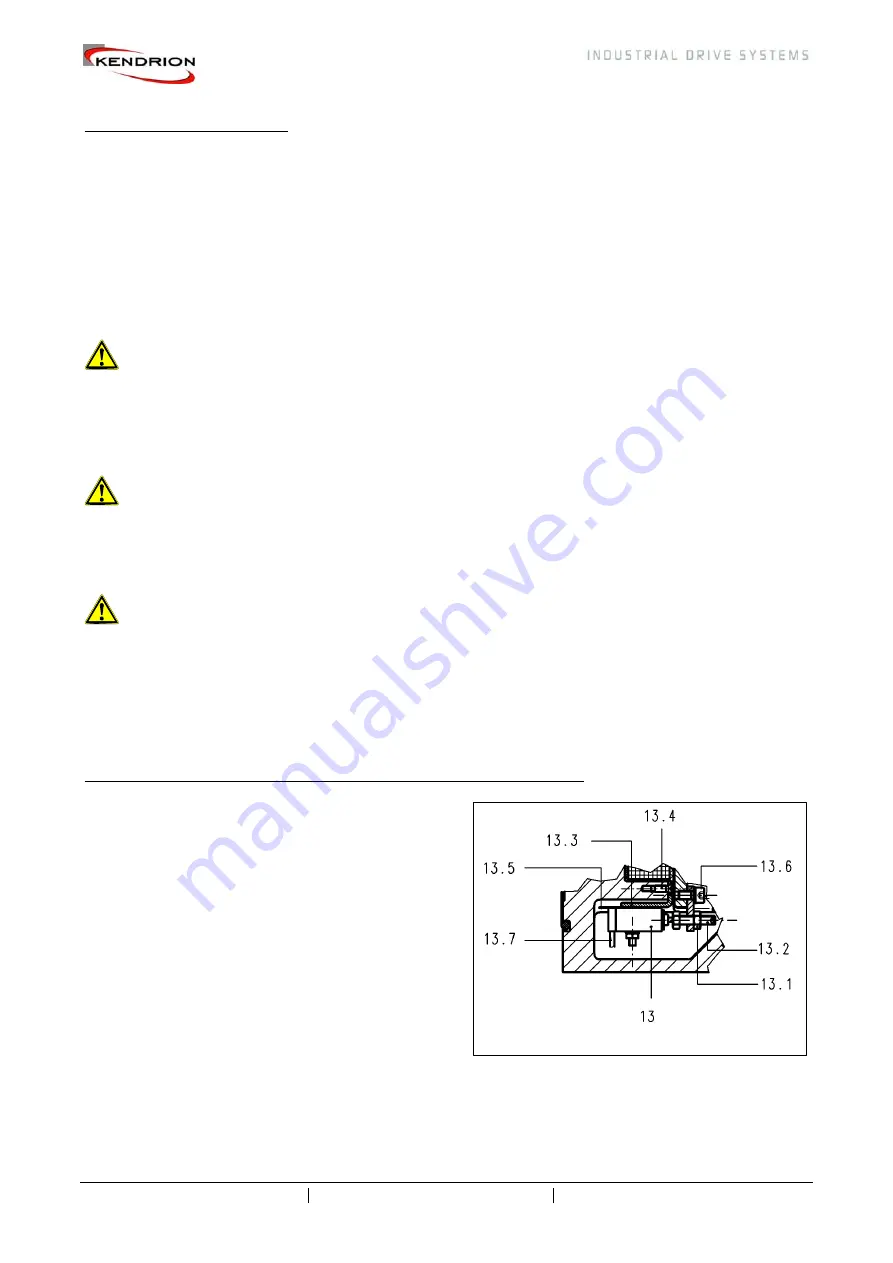
Microswitch (13) adjustment or replacement (only brakes with microswitch):
The spring-applied single-disc brake must be released
electrically to allow the microswitch (13) to be adjusted.
Loosen the machine screws (20) provided on the cover
(7) and remove the cover (7). Unscrew the locknut
(13.1) and turn the set screw (13.2) clockwise until the
microswitch (13) switches (slight audible click or contact
closure between contacts 5 and 6 (see Section 3.3). If
the microswitch (13) is in ON position, it must be turned
anticlockwise to OFF. After the changeover position has
been reached, continue to turn the set screw (13.2) by
60° to 90°. Tighten the locknut (13.1). Make sure the set
screw (13.2) position remains unchanged when
tightening the locknut. Switch the brake on and off to
check that the microswitch is in perfect working order. If
the microswitch (13) needs to be replaced (e.g. when
the maximum service life (switching operations) has been reached) (see "Technical specifications"), such
work must be carried out by the manufacturer or by an authorised repair shop due to the difficult installation
of the microswitch with the four thermoswitches (11 and 12).
Fig. 19/1: Microswitch adjustment


