background image

7

A7 MIG Welder

© Kemppi Oy 2020

2002

INTEGRA

TION GUIDE

3.3  Power source

Place the machine on a sturdy, level surface that is dry 

and will not allow dust or other impurities to enter the 

machine’s cooling air flow. Preferably, situate the machine 

in a suitable carriage unit so that it is above floor level.

•  The surface inclination may not exceed 15 

degrees.

•  Ensure the free circulation of cooling air. There 

must be at least 20 cm of free space in front 

of and behind the machine for cooling-air 

circulation.

•  Protect the machine against heavy rain and direct 

sunshine.

  Do not operate the machine in the rain.

  Never aim the spray of sparks from a grinding machine 

toward the equipment.

The power plug

The power source comes without a plug for connection 

to the electrical grid. Attach a plug suitable for your 

power-supply standard to the power cable. Check the 

connections, attach the plug to a socket, and switch the 

electrical power on from the welding power source to 

verify that the machine works properly.

  Switch the machine off, and unplug it from the power 

socket before continuing to further steps in the hardware 

installation.

  If local or national regulations specify that an 

alternative power cable is required, the cable must be 

replaced in conformity with the regulations. Connection 

and installation of the power cable and plug should be 

carried out only by a suitably qualified person. 

Remove the machine’s left-hand cover plate to enable 

attachment of an electrical cable. The power source unit 

can be connected to a 400 V, 3~ power supply.

If changing the power cable, take the following facts 

into consideration:

•  The cable enters the machine through the inlet 

ring on the rear panel and is fastened in place 

with a cable clamp (05). 

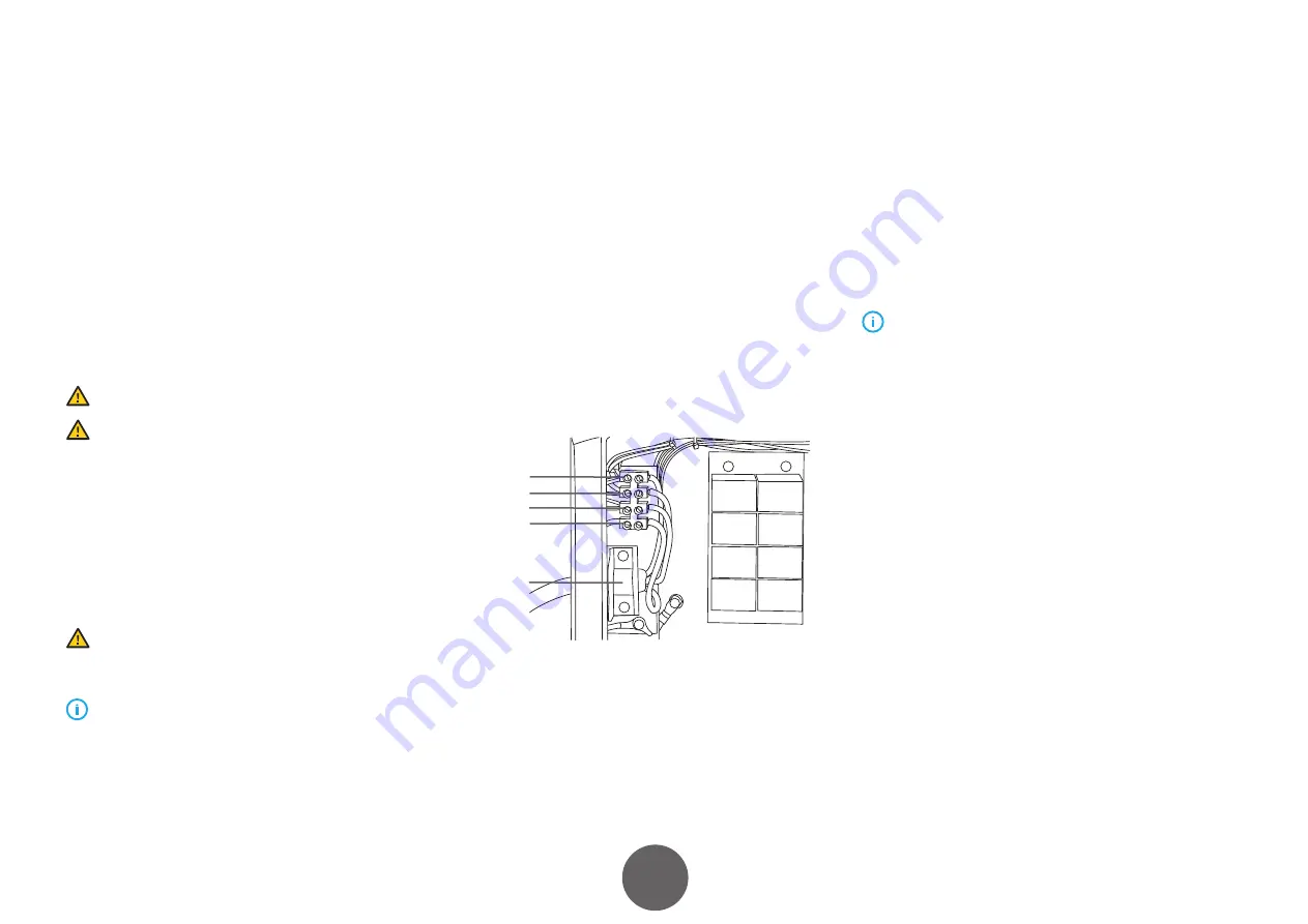
•  The phase conductors of the cable are coupled to 

connectors L1, L2, and L3.

•  The protective ground line, colored green and 

yellow, is coupled to the marked connector.

•  If you are using five-lead cable, do not connect 

the neutral conductor. 

05

*

L3

L2

L1

*

 In S-type cables there is a protective grounding conductor, 

green-and-yellow striped.

3.4  Cooling unit

If you use a water-cooled welding torch, you need a 

cooling unit installed as part of the welder system. Attach 

the cooling unit to the power source. See the detailed 

installation instructions in the operating manual delivered 

with the cooling unit package.

The cooling hose connections are described in 

Subsection 

3.8.5, “Cooling hoses.”

  The wire feeder has no connectors for cooling hoses. 

Use a special adapter to connect the cooling hoses to the 

welding torch cooling connectors.

3.5  Wire feeder

Use a two-part mounting bracket to mount the wire 

feeder securely on the robot arm. Fasten the upper part of 

the bracket to the bottom of the wire feeder and the lower 

part to the robot arm. Finish the installation by putting the 

bracket parts together and fixing them in place with bolts. 

See the illustrated instructions included in the product 

delivery package.

Mounting brackets are available for the most commonly 

used welding robots. See the complete list at 


www.kemppi.com

.

The wire feeder connections are described in 

Section 3.8, 

“Interconnection cable set.”

Содержание A7 350

Страница 1: ...350 450 1920310 2002 A7 MIG Welder A7 MIG Welder EN INTEGRATION GUIDE...

Страница 2: ...he Web user interface 20 4 1 Configuring the network settings 20 4 2 Opening the web user interface 21 5 System configuration 22 5 1 Welding system sensors and devices 22 5 1 1 General settings 22 5 1...

Страница 3: ...ldingVoltage 47 6 2 3 WeldingWireFeedSpeed 47 6 2 4 MotorCurrent 47 6 2 5 GasFlowRate 47 6 2 6 ErrorNumber 47 6 2 7 WeldingMemoryChannel 48 6 2 8 TAST 48 6 2 9 WeldingProcess 48 6 2 10 Ready 48 6 2 11...

Страница 4: ...notice Do not copy record reproduce or transmit the contents of this guide without prior permission from Kemppi The web user interface server part of the robot interface unit is meant to be used only...

Страница 5: ...face unit use the recesses at both ends of the robot interface unit After installation make sure all cables and hoses have enough space to move and are attached properly Remember that the cable plugs...

Страница 6: ...6 A7 MIG Welder Kemppi Oy 2020 2002 INTEGRATION GUIDE Fieldbus Figure 3 1 Connection diagram gas cooled system Fieldbus Figure 3 2 Connection diagram water cooled system...

Страница 7: ...ectrical cable The power source unit can be connected to a 400 V 3 power supply If changing the power cable take the following facts into consideration The cable enters the machine through the inlet r...

Страница 8: ...e described later in this document Figure 3 3 Peripheral connector pinout A Motor B Motor C Supply 24 V D Wire inch input E Collision sensor input F Touch sensor output for gas nozzle 50 200 V G Tacho...

Страница 9: ...rate properly the push pull torch must be configured for use The configuration is described in Subsection 5 1 4 General robot settings M A B Figure 3 4 Push pull motor connection S M A B G J I Figure...

Страница 10: ...sensor See the manual of the robot mount for more information The welder system supports two types of collision sensors an opening action switch sensor and a closing action switch sensor The opening...

Страница 11: ...asurement input connector at the rear of the power source Connect the cable to the arc measurement output connector at the wire feeder For using the arc voltage calibration connect a separate earth ca...

Страница 12: ...e robot interface unit Do not use any other control cable connectors 3 8 3 Welding cable The welding cable delivers welding power from the power source to the welding head At the wire feeder connect t...

Страница 13: ...ure 3 13 Installing a fieldbus adapter Ensure that it sits properly in its place Tighten the two screws on the module after you have placed it into the slot Connect a suitable fieldbus cable to the co...

Страница 14: ...n this situation The touch sensor voltage is automatically lowered to a safety level max 110 V After a gate door switch action the system is recovered automatically Both inputs have a separate three p...

Страница 15: ...ut can be used for better response For connection of fast status output the robot must have at least one hardware input available Connect the fast output to the touch sensor fast status output connect...

Страница 16: ...IG Welder supports two wire feeders one operational at the time This feature is enabled by an optional extension kit The extension kit is installed inside the robot interface unit The kit includes a w...

Страница 17: ...n by amber LED lights After successful installation switch the power source off and close the robot interface unit Follow these steps to install the extension kit 7 Unscrew four screws two from the fr...

Страница 18: ...01 X7 X4 X4 X7 A105 A102 15 Plug a touch sensor cable between the switching card A105 input and the touch sensor card output A102 X2 X5 A102 A101 X2 X5 A105 A102 16 Plug a bus cable between the switch...

Страница 19: ...in serial In parallel the water flow can differ between the torches and may cause damage to the torch The extension kit includes support for water valves Should you want to use valves to control the c...

Страница 20: ...you specify the IP settings manually When the DHCP client is switched on it takes some time for the client to establish a connection to the DHCP server and retrieve the address information Usually the...

Страница 21: ...the address bar for example http 10 0 0 20 If the network cable is connected and the network settings are configured properly the network browser opens the web user interface and redirects to the weld...

Страница 22: ...ling up the cooling system Choose AUTO for normal operation with a water cooled system Welding cable length Set the welding cable length in meters The cable length includes the welding and welding cab...

Страница 23: ...m indicates that the gas flow is OK Gas type integrated gas sensor Set the type of the shielding gas used in your configuration This value must be changed every time the gas type is changed The gas ty...

Страница 24: ...parameter to be OFF to prevent possible false detection Switch type Select the type of the switch used in your collision sensor The switch can be either OPENING or CLOSING See Figure 3 8 Opening acti...

Страница 25: ...elding system stops welding if the robot stops sending fieldbus data The robot must perform continuous transitions on the Watchdog signal of the digital robot interface within the timeout period 5 1 9...

Страница 26: ...GWelder system and a welding robot is based on input output tables I O tables exchanged between the machines by fieldbus cyclic I O transmission The tables contain binary level functions that the robo...

Страница 27: ...ltage status function WeldingCurrent status function For more information on these functions see Chapter 6 Digital robot interface I O reference To set up the scaling values go to Welding settings Wel...

Страница 28: ...in accuracy of one decimal digit thus the calculation loses less significant digits and produces final values which may not exactly match with the target values Example By means of its specification o...

Страница 29: ...r all users including the Admin user is 0000 four zeroes Require users to change their PIN code at the first login To continue with user configuration log in to the web user interface by providing the...

Страница 30: ...system it is a good idea to make a system backup file The backup file can save significant time if the memory channels welding system settings user settings and or network settings need to be restore...

Страница 31: ...0 Watchdog WeldingWireFeedSpeed 1 ErrorReset 2 AirBlow 3 Not in use 4 Not in use 5 DigitalOutput1 6 DigitalOutput2 7 DigitalOutput3 5 6 2 KEMPPI2 KempArc Pulse customized table Interface mode 13 Tabl...

Страница 32: ...0 Dynamics CycleOn 1 ArcOn 2 TouchSensed 3 PowerSourceReady 4 Error 5 Ready 6 LocalRemote 7 AutoManual 6 0 StartWelding GateDoorOpen 1 SimulationMode DigitalInput2 2 WireInch DigitalInput3 3 WireRetra...

Страница 33: ...Sel Not in use 7 TouchSensorOn TouchSensed 7 0 OnlineControl GateDoorOpen 1 ErrorReset Error 2 WireFeederSelect CollisionDetected 3 Watchdog Not in use 4 HotStartOn Not in use 5 CraterFillOn Not in us...

Страница 34: ...t in use 7 TouchSensorOn TouchSensed 7 0 OnlineControl GateDoorOpen 1 ErrorReset Error 2 WireFeederSelect CollisionDetected 3 Watchdog Not in use 4 HotStartOn Not in use 5 CraterFillOn Not in use 6 No...

Страница 35: ...se Not in use 8 WireFeedSpeed WeldingCurrent 9 10 Voltage FineTuning WeldingVoltage 11 12 Not in use Not in use 13 14 Not in use Not in use 15 5 6 7 CUST2 Customer specific table Interface mode 5 Tabl...

Страница 36: ...4 Customer specific table Interface mode 7 Table size 10 bytes Byte Bit Control Robot Welder Status Welder Robot 0 0 WeldingAllowed PowerSourceReady 1 ErrorReset Error 2 StartWelding ArcOn 3 Simulatio...

Страница 37: ...cleOn 3 Not in use MainCurrentOn 4 Not in use CollisionDetected 5 Not in use PowerSourceReady 6 Not in use Ready 7 Not in use Not in use 2 0 Not in use WireStuck 1 Not in use TouchSensed 2 Not in use...

Страница 38: ...X X X X X Voltage 16 80 460 1 0 1 V X X X X X X X X X X FineTuning 16 0 180 1 0 1 X X X X X X X X X X Dynamics 8 0 18 1 1 X X X X X MemoryChannel 7 8 0 199 1 8 8 8 8 8 8 7 8 8 8 PulseCurrent 16 99 800...

Страница 39: ...d speed value is calculated from the setup value by means of the value scaling formula This value has an effect only when the OnlineControl signal is set 1 and it overrides the corresponding memory ch...

Страница 40: ...rol signal is cleared 0 the fine tuning from the active memory channel is used 6 1 4 Dynamics This 8 bit function controls the dynamics of the synergic curve for all processes exceptWiseRoot The root...

Страница 41: ...ble and disable the StartWelding signal When the value is 1 welding allowed the StartWelding signal controls welding start and stop When the value is set to 0 welding disallowed the StartWelding signa...

Страница 42: ...has no effect during welding or simulated welding 6 1 17 TouchSensorToolSel This signal function sets the selection of the touch sensing tool between the welding wire and the gas nozzle if the tool i...

Страница 43: ...ror reset on rising edge 6 1 22 HotStartOn This signal function controls a hot start on and off if the hot start is enabled to be controlled by a robot from the web user interface or from the setup pa...

Страница 44: ...I O table Min Max Step Units KEMPPI 1 KEMPPI 2 KEMPPI 3 KEMPPI 4 KEMPPI 5 CUST1 CUST2 CUST3 CUST4 CUST5 1 13 14 15 16 3 5 6 7 9 Status values WeldingCurrent 16 0 1024 1 1 A X X X X X X X X X X Welding...

Страница 45: ...eady 1 X X X X X X X X X X PowerSourceReady 1 X X X X X X X X CoolingUnitOk 1 X ProgramSaved 1 X RobotHasControl 1 X CycleOn 1 X X X X X X X X X X ArcOn 1 X X X X X X X X X X GasFlowOk 1 X X X X X X X...

Страница 46: ...T3 CUST4 CUST5 1 13 14 15 16 3 5 6 7 9 Status bits DigitalInput1 1 X X X X X DigitalInput2 1 X X X X X X X X X DigitalInput3 1 X X X X X X X DigitalInput4 1 X X X X X X X DigitalInput5 1 X X X X X X X...

Страница 47: ...user setup In non scaled mode The minimum value is 0 0 0 m min The maximum value is 250 25 0 m min The minimum step is 1 0 1 m min In scaled mode The minimum value is 0 0 0 m min The maximum value is...

Страница 48: ...and errors are resolved 1 Welding system ready 6 2 11 PowerSourceReady This signal function indicates the status of the power source The power source is ready to start welding when it is not currently...

Страница 49: ...ithin the limits set by a user 0 Wire feed speed too low or too high 1 Wire feed speed within the limits This function is not implemented in the A7 MIG Welder The status is always OK 1 6 2 22 TouchSen...

Страница 50: ...e weld 0 Wire is OK 1 Wire is stuck This function is not implemented in the A7 MIG Welder The status is always OK 0 6 2 27 GateDoorOpen This signal function indicates whether the gate door is open or...

Страница 51: ...Digital robot interface function timing B StartWelding CycleOn ArcOn B StartWelding CycleOn ArcOn Symbol Description Min Typical Max Units A Cycle on time 6 17 40 ms B Arc establishment time 17 Pre ga...

Страница 52: ...time 3 14 20 ms B MIG logic process 5 ms B Setup time Gas valve on 1 ms B Setup time Pre gas time going 1 ms B Setup time Set wire feed on 1 ms B Setup time Set power source on 1 ms B Setup time Cree...

Страница 53: ...interface function timing A B StartWelding CycleOn ArcOn Symbol Description Min Typical Max Units A Arc off time 51 51 94 ms B Cycle off time 347 Post gas time 10 Pre gas time 44 ms The minimum cycle...

Страница 54: ...ArcOn D F2 Symbol Description Min Typical Max Units A Weld start response time 3 3 20 ms B MIG logic process 4 ms B Setup time Post gas time going 1 ms B Setup time Set power source off 1 ms B Setup t...

Страница 55: ...ry channel data Load curve data MemoryChannel Apply curve data A B C Active value Ready to weld Ready to weld Welding system T Symbol Description Min Typical Max Units T Total time 380 392 500 ms A Me...

Страница 56: ...ol data setup time 27 30 50 ms Switching offline memory channel mode Welding system Load setup file Online Memory channel mode Robot mode Load memory channel data Load curve data Apply new data C D B...

Страница 57: ...onse time 3 ms B Wire feeder motor acceleration time 3 s The wire feeder reacts on controls immediately after startup The acceleration time depends on the selected wire feed speed Stop timing Welding...

Страница 58: ...Ready B New tool Ready Touch sensor Symbol Description Min Typical Max Units A Control response time 3 ms B Relay action time 5 ms Touch response timing B Short circuit touch Fast status output TouchS...

Страница 59: ...ing system STOPPED Operating ERROR Error ErrorNumber EMERGENCY STOP 133 NO ERROR 0 D Symbol Description Min Typical Max Units A Hardware response time 500 s B Error setup time 10 ms C Welding system s...

Страница 60: ...And you know...

Отзывы: