Operating Manual AmbiCube
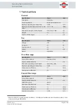
Functional description
Page 14 of 40
Version: 2 | en
Subject to technical changes
4 Functional description
4.1 General
The system is designed to remove the finest particles from the room air. The finest
particles include fine dust, pollen, bacteria and viruses.
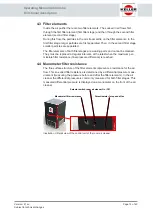
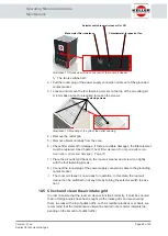
Blow-out opening
Second filter stage
First filter stage
Fan
Air intake openings
Illustration 1:
Sectional view of the room air cleaner
A fan is installed inside the room air cleaner. When the room air cleaner is
switched on, the built-in fan is switched on. The fan creates a negative pressure,
whereby the room air is sucked through the intake openings into the interior of the
room air cleaner.
After entering the room air cleaner, the air flows through the fan and then through
the filter elements of the first and second filter stage. After passing through the filter
elements, the cleaned air exits the room air cleaner at the top.
4.2 Fan
The fan generates the negative pressure required for the air volume flow. The
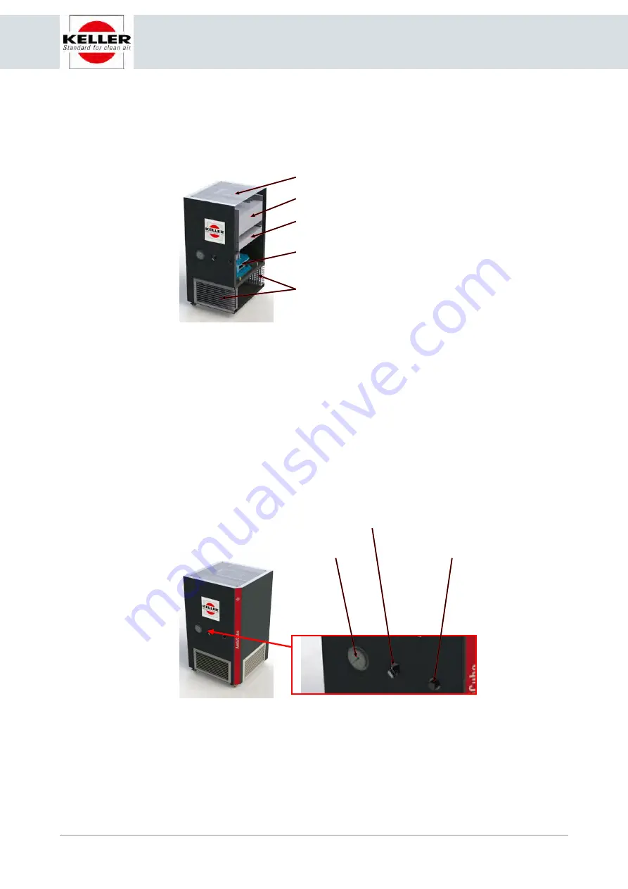
speed of the fan can be adjusted by a potentiometer. The potentiometer is located
on the front of the room air cleaner, directly next to the on/off switch.
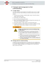
Selector switch room air cleaner On / Off
Manometer filter resistance
Potentiometer for speed of fan
Illustration 2:
Detail view of the control unit of the room air cleaner
By changing the speed of the fan, the air volume flow and the negative pressure
are influenced. This allows the extracted air volume flow and the number of air cir-
culations per hour to be adapted to the size of the room.

