4 APP Operation
Hybrid Inverter
User Manual
76
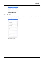
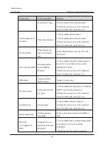
Figure4-41 Battery setting
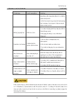
4.3.4 Grid Setting
In the grid setting item, you can set grid mode including P-V mode, Q-V mode, SPF mode and
schedule mode. As shown in Figure4-42.
Figure4-42 Grid setting
Страница 1: ...i iStoragE1 Series Hybrid inverter User Manual...
Страница 2: ......
Страница 3: ...document may not be within the purchase scope or the usage scope Unless otherwise specification in the contract all statements information and recommendations in this document are provided AS IS with...
Страница 4: ...figures in this manual are just for reference for details please see the actual product Suitable Model iStoragE1 3600 iStoragE1 5000 iStoragE1 6000 The energy storage system iStoragE1 series consists...
Страница 5: ...low risk hazard that could if not avoided result in minor injury Anti static prompting Be care electric shock prompting Provides a tip that may help you solve a problem or save time Provides addition...
Страница 6: ...roof Protection 5 1 1 7 Safety Warning Label Setting 5 1 1 8 Electrical Connection 5 1 1 9 Measurement Under Operation 6 1 2 Safety Precaution for Battery Pack 6 1 2 1 General Safety Precautions 6 1 2...
Страница 7: ...ng 18 3 4 Mechanical Installation 20 3 5 Electrical Connection 30 3 5 1 Components Requirement 31 3 5 2 External Grounding Connection 31 3 5 3 DC Input PV Connection 32 3 5 4 AC Output Connection 35 3...
Страница 8: ...7 5 1 Startup 77 5 2 CEI Self Check 79 5 3 Shutdown 82 6 Maintenance and Troubleshooting 83 6 1 Maintenance 83 6 2 Troubleshooting 84 7 Package Transportation and Storage 92 7 1 Package 92 7 2 Transpo...
Страница 9: ...lease read the announcements and operation instructions in this section carefully to avoid accident The promptings in the user manual such as Danger Warning Caution etc don t include all safety announ...
Страница 10: ...k if the inverter is damaged or has other danger Check if the external device or circuit connection is safe Before checking or maintenance if the DC side and AC side is power down just now it is neces...
Страница 11: ...ical voltage The product operates at high voltages WEEE designation Do not dispose of the product together with the household waste but in accordance with the disposal regulations for electronic waste...
Страница 12: ...between inverter and PV array has been disconnected completely And set warning mark in the disconnected position to avoid reconnecting 1 1 4 ESD Protection To prevent human electrostatic damaging sen...
Страница 13: ...rve the following requirements while installing maintaining or repairing Set warning marks where the switches are to avoid switching them on improperly Set warning signs or safety warning belt in the...
Страница 14: ...of breakdown of the battery may lead to a leakage of electrolyte or flammable gas Battery pack is not user serviceable High voltage is present in the device Read the label with Warning Symbols and Pr...
Страница 15: ...m battery and not spread to it yet Fire fighting instructions If fire occurs when charging batteries if it is safe to do so disconnect the battery pack circuit switch to shut off the power to charge I...
Страница 16: ...the service life detail please see 3 2 2 Installation Environment If the installation environment does not meet the requirement the guarantee time may be influenced The used environment may influence...
Страница 17: ...Intro With energy storage system iStoragE1 series it is possible to effectively manage energy in users home day and night This energy storage system will provide a complete energy solution with multip...
Страница 18: ...insufficient or no PV power battery discharge to load Time of use mode iStoragE1 product can meet the maximum energy utilization rate and users income According to peak valley electricity price and us...
Страница 19: ...StoragE1 product will be in standby status Off grid mode iStoragE1 product can be operated in a completely off grid mode where no grid power is available The above modes are only functional definition...
Страница 20: ...ue ON the system works normally Flicker 1s inverter alarm Flicker 3s inverter standby 2 2 4 Inverter Structure Layout Illustration The external terminals and switch of inverter as shown in Figure2 2 F...
Страница 21: ...utput terminal It is used to connect with grid BACKUP AC output terminal It is used to connect with load PV1 PV2 DC input terminal It is used to connect with PV DC switch DC switch Can be removed unde...
Страница 22: ...coupled system and fully off grid system as shown in Figure2 3 Figure2 4 and Figure2 5 Meter Grid Off grid load INV BAT On grid load PV array Figure2 3 DC coupled system Meter Meter Grid PV array PV...
Страница 23: ...n This chapter introduces the installation of the device including installation process installation preparation transportation and unpacking installation procedure electrical connection and checking...
Страница 24: ...3 Installation Hybrid Inverter User Manual 16 3 2 Installation Preparation 3 2 1 Tools Tools Tape Levelling instrument Goggles Torque wrench...
Страница 25: ...1 The iStoragE1 product is rated at IP65 for outdoor and indoor installation But if the iStoragE1 product is installed under directly sunshine its temperature will rise quickly so do not install the...
Страница 26: ...ng site in advance In principle the unpacking site should be as close to the installation site as possible The device has been tested and checked strictly but it still may be damaged during transporti...
Страница 27: ...s there are three snap magnetic rings two on the PV side and one on the battery input side The smallest magnetic ring is connected to communication port according to manual operation instructions and...
Страница 28: ...pack is not handled properly during transporting Keep the installed place far away from the tube of water electricity or gas which is to avoid affect the installation When installing please wear safet...
Страница 29: ...ule and battery packs Figure3 7 Tear back glue Figure3 8 Mark the installation holes Step 3 Remove the position boards and auxiliary tool Step 4 Drill four holes on the wall and drill two holes in the...
Страница 30: ...use gasket to make the floor horizontal Ensure that the installed wall is flat and horizontal flatness within 4mm and the installed floor horizontal angle is 0 If not please use gasket to make the flo...
Страница 31: ...ce is installed on the low lying position and may have the risk of soaking by rain we suggest to select the support to lift the device to avoid damage for the device The installation of support is as...
Страница 32: ...on bolt M10 as shown in Figure3 15 Figure3 15 Mark the installation holes 4 Assemble the support and base by screws M5 as shown in Figure3 16 Figure3 16 Assemble the support and base During drilling p...
Страница 33: ...above figure we take standard configured base as an example to illustrate Step 7 Install battery packs 1 Fix the bottom battery pack with base by wall bracket b as shown in Figure3 17 Figure3 17 Fix...
Страница 34: ...he wall the bottom limit holes of the upper battery pack should match the screw on the top of the below battery pack as shown in Figure3 19 Figure3 19 Place the battery pack 4 Tighten the battery rack...
Страница 35: ...Manual 3 Installation 27 Step 8 Install the inverter 1 Mark the positions of the drill holes with the inverter positioning board Figure3 21 Place inverter positioning board Figure3 22 Mark the invert...
Страница 36: ...on plugs 8 40 into the drill holes Figure3 23 Insert the expansion plugs unit mm 3 Attach the wall bracket to the wall using seven M5 Self tapping screws with the tool of screwdriver as shown in Figur...
Страница 37: ...ect the wires between the inverter and battery packs While connecting the inner wires of system it is necessary to make the handle on the battery pack vertical to the side and lead the battery and BMS...
Страница 38: ...take 1 inverter 2 battery packs as an example to illustrate The wiring of other configuration is the same End You can install extra batteries up to 8 batteries in a system Please install extra batteri...
Страница 39: ...00VA 32A for 6000VA Purchased by the installer RCD Type B 30mA 0 3S Purchased by the installer 3 5 2 External Grounding Connection The external grounding terminal of inverter as shown in of Figure2 2...
Страница 40: ...e the same the two need to be separated as shown in Figure3 30 or lightning stroke will damage the inverter The grounding of the inverter should be directly connected to the grounding system and the i...
Страница 41: ...g positive metal terminal and negative terminal corresponding procedure as follows Step 1 Strip the insulation layer of positive wire and negative wire for about 7mm as shown in Figure3 31 Figure3 31...
Страница 42: ...igure3 34 Tighten the sealing nuts Step 5 Measure the voltage and check if the positive and negative is connected properly and if the voltage within the input range of the inverter Step 6 Insert the p...
Страница 43: ...ion Model AC input specification GRID AC output specification BACKUP iStoragE1 3600 32A 20A iStoragE1 5000 50A 25A iStoragE1 6000 63A 32A During wiring please pay attention to distinguish the AC live...
Страница 44: ...connector installation 2 Step 5 Inserted the unlock key into socket and insert seal and Clamp Finger into socket and then tighten the nut Figure3 39 GRID connector installation 3 Step 6 Connect the G...
Страница 45: ...Wire Stripping unit mm Step 3 Set the parts on the cable Figure3 42 Insert the BACKUP terminals Step 4 Crimp wires screw push housing into body and locker rotate outward 15 Figure3 43 BACKUP connecto...
Страница 46: ...for registration or take photos of the QR code on the WiFi module in advance to prevent users from being unable to scan the code after the side cover is installed The inverter is equipped with WIFI i...
Страница 47: ...please see the built in user manual in the packaging of WIFI 3 5 6 Communication Port Connection Communication ports include DRM port Meter port and BMS port they all adopt RJ45 plug to connect The pi...
Страница 48: ...ter still can t communicate after connecting you need to recheck if the crimping is correct DRM port DRM communication port is used to connect the DRM controlling device When using DRM port the PIN7 a...
Страница 49: ...3 Installation 41 Figure3 50 Connection diagram between communication smart meter and inverter and grid single phase Figure3 51 Connection diagram between communication smart meter and inverter and gr...
Страница 50: ...ion diagram between communication smart meter and inverter and grid three phase single phase For the actual wiring of the smart meter see the diagram on the right side of the meter The manual uses Chi...
Страница 51: ...e PV inverter grid side address is set to A 002 When there is a PV inverter in the user s home it is recommended to install the smart meter in the grid output side of the PV inverter to ensure the acc...
Страница 52: ...ntrol power The pin illustration of smart meter is as shown in Step 1 and Table3 5 Table3 4 Pin illustration of smart meter single phase Pin Illustration 3 Connect to phase L of GRID port in the inver...
Страница 53: ...nect to I port of current transformer of grid output L1 16 Connect to I port of current transformer of grid output L2 17 Connect to I port of current transformer of grid output L2 19 Connect to I port...
Страница 54: ...follows Step 1 Unscrewing the lock nut insert the RJ45 port to the communication port after through the magnetic ring and COM wiring cover as shown in Figure3 58 Figure3 58 Insert the communication p...
Страница 55: ...ten them to avoid extruding for the wires and even cause damage for the wires and affect the normal use Figure3 60 Tighten the wiring cover plate Ensure that the installed wall is flat and horizontal...
Страница 56: ...site to download the APP and do WIFI configuration Download APP APPSTORE https apps apple com cn app wisesolar plus id1510470362 GOOGLE PLAY https play google com store apps details id com kehua wises...
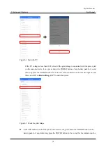
Страница 57: ...cording to prompting Logger code can be entered by scanning the QR code of WIFI on the device Step 3 After registering login according to the registered mobile phone Email and password as shown in Fig...
Страница 58: ...ion Hybrid Inverter User Manual 50 Figure4 2 Main page Step 5 After entering corresponding information select Save and exit button as shown in Figure4 3 Figure4 3 Create your plant page The item with...
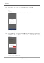
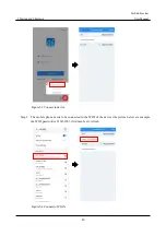
Страница 59: ...he electricity price in the future Step 6 Back to main page and click the Built plant as shown in Figure4 4 Figure4 4 Home interface Step 7 Select Add device to scan the QR code of the collector the d...
Страница 60: ...n page then click Connect to device and then click Connect at the top of the page it will show the Wi Fi list Select the Wi Fi whose name is the same as that of WIFI module and then enter the default...
Страница 61: ...ick Logger WiFi select a available WiFi in Hotpot list when it prompts WiFi connecting successful click OK At this time the currently connected WiFi should show Connected Figure4 7 Configure WiFi Step...
Страница 62: ...ve steps click corresponding SN to view the inverter information Figure4 9 Inverter information interface Step 2 Pull down the interface and click the More Data button to see more information such as...
Страница 63: ...ation In the PV information item you can view PV voltage PV current and PV power etc as shown in Figure4 11 Figure4 11 PV information Inverter information In the inverter information item you can view...
Страница 64: ...Inverter User Manual 56 Figure4 12 Inverter information Grid information In the running information item you can view load voltage load current grid tied apparent power etc as shown in Figure4 13 Figu...
Страница 65: ...rrently running software version in Control software 1 version and Control software 2 version of Device information Figure4 14 Device information Query Select standard type In the Basic parameter sett...
Страница 66: ...actor mode and reactive power mode setting In the Reactive power mode of Basic parameter setting item if it is set to Scheduling by SI reactive power mode is enabled and if it is set to Scheduling by...
Страница 67: ...V mode to enable Volt watt response mode Volt watt response mode is for charging of multiple mode inverter with energy storage When connecting the multiple mode inverter the two internal N wires shou...
Страница 68: ...verter User Manual 60 Figure4 19 P V mode Password authentication required for setting changes Password authentication is required when modifying parameters the password is login password 1 Figure4 20...
Страница 69: ...wer etc of battery pack as shown in Figure4 21 Figure4 21 Battery pack info page The address of DCDC module address is 1 2 3 4 5 can be set through APP according to needs The setting is in the operati...
Страница 70: ...switch to more page select DCDC Address Configuration and then enter the number of batteries to be configured as shown in Figure4 23 Figure4 23 Set the battery number Step 3 Click bottom Add device bu...
Страница 71: ...ddress of first DCDC module is 1 the second one is 2 and so on Figure4 24 Set the address Step 5 After the address of all DCDC modules is entered the bottom Add device button will turn to gray click O...
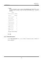
Страница 72: ...ery pack 1 info S N If the setting is successful the S N will change to the S N of the device whose address is set to 1 as shown in Figure4 26 Figure4 26 Check the setting End 4 2 2 Status Information...
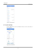
Страница 73: ...ual 4 APP Operation 65 Figure4 27 Status information 4 3 Control Interface Click the Control button in the inverter information interface to enter the control interface as shown in Figure4 28 Figure4...
Страница 74: ...F setting mode setting and BMS communication setting Figure4 29 Basic parameter setting Mode can be set to time of use mode backup mode self consumption mode energy scheduling mode external control mo...
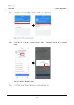
Страница 75: ...Hybrid Inverter User Manual 4 APP Operation 67 Figure4 30 Time of use mode End Backup mode Step 1 Choose Disable in External control mode Step 2 Choose Backup mode in Work mode...
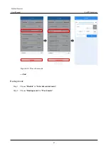
Страница 76: ...4 APP Operation Hybrid Inverter User Manual 68 Figure4 31 Backup mode End Self consumption mode Step 1 Choose Disable in External control mode Step 2 Choose Self Consumption in Work mode...
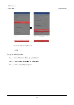
Страница 77: ...APP Operation 69 Figure4 32 Self consumption mode End Energy scheduling mode Step 1 Choose Disable in External control mode Step 2 Choose Energy scheduling in Work mode Step 3 Set the corresponding ti...
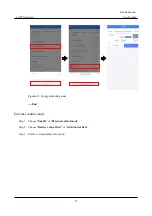
Страница 78: ...Manual 70 Figure4 33 Energy scheduling mode End External control mode Step 1 Choose Enable in External control mode Step 2 Choose Battery control first or Grid control first Step 3 Set the correspond...
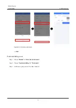
Страница 79: ...71 Figure4 34 External control mode End Peakload shifting mode Step 1 Choose Disable in External control mode Step 2 Choose Peakload shifting in Work mode Step 3 Set the max grid power in Set Max Gri...
Страница 80: ...ing can prevent inverter from releasing the backup power of battery pack Set the value of SOC threshold for power switching value in SOC threshold for power switching according to actual situation onc...
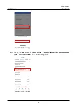
Страница 81: ...lease contact the installer to set the baud rate and address of the meter The setting is in the operation maintenance authority and needs to be set by installer The setting procedure is as follows Ple...
Страница 82: ...er User Manual 74 Figure4 37 Set the meter type Step 2 Set the baud rate of meter in System setting Communication baud rate of grid side meter Bps The default baud rate is 9600 as shown in Figure4 38...
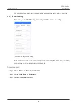
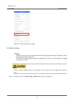
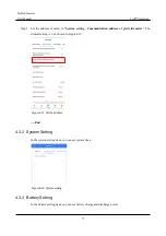
Страница 83: ...tion address of grid side meter The default setting is 1 as shown in Figure4 39 Figure4 39 Set the address End 4 3 2 System Setting In the system setting item you can set system time Figure4 40 System...
Страница 84: ...d Inverter User Manual 76 Figure4 41 Battery setting 4 3 4 Grid Setting In the grid setting item you can set grid mode including P V mode Q V mode SPF mode and schedule mode As shown in Figure4 42 Fig...
Страница 85: ...ternal PV switch Step 5 Before start the inverter you should set the inverter function via APP battery setting and basic parameter setting The mode can be set to time of use mode backup mode self cons...
Страница 86: ...OWER button of any battery pack for 1s and then long press the POWER button for 5s to wait for the indicator on the inverter light on and then select ON in Basic setting of APP to start the system Fig...
Страница 87: ...e Step 8 About 60s the inverter will generate power normally LED is always on Step 9 Working status can be queried on the APP End 5 2 CEI Self Check The iStoragE1 product has the CEI self check functi...
Страница 88: ...ter User Manual 80 Figure5 3 Connect to device Step 2 The mobile phone needs to be connected to the WIFI of the device the picture below are example the WIFI password is 12345678 if it doesn t exit re...
Страница 89: ...r interface and then click Customer Figure5 5 Enter the customer interface Step 4 Click Start in the monitor interface and click Done in the popup Then the device starts self check Figure5 6 Start the...
Страница 90: ...started independently please perform the follow operation Shut down the battery pack When the PV or grid has power the battery pack won t be power down When the PV and grid without power it is necess...
Страница 91: ...injury After shut down the inverter and wait until it cooling down then do the maintenance and clean Do not clean the inverter with any solvent abrasive material or corrosive material Normally the inv...
Страница 92: ...d in particular the cable jackets touching the metallic surface are not scratched 3 Unused PV input terminals unused communication ports of the inverter power and COM terminals of the battery pack are...
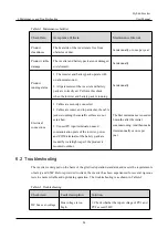
Страница 93: ...e impedance is less than 25K check whether the connection of each port is correct 4 Confirm to install the device according to the user manual 5 Restart the inverter to see if the fault still exists I...
Страница 94: ...ts If it still exists contact customer service RTC abnormal Clock chip abnormal 1 After powering off and restarting check whether it is abnormal 2 Restart the inverter to see if the fault still exists...
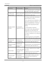
Страница 95: ...e fault still exists contact service BMS communication fault Abnormal communication with BMS Check whether communication wire between BMS and inverter is loosed Battery inner fault Shutdown fault from...
Страница 96: ...ter to see if the fault still exists If it still exists contact service Overload Load is too large 1 Check whether the load exceeds the rated power 2 Restart the inverter to see if the fault still exi...
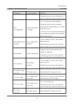
Страница 97: ...is low automatic recovery after operating for a while 2 Restart the inverter to see if the fault still exists If it still exists contact service DRM alarm Powered off after DRM enabled Normal no proc...
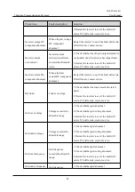
Страница 98: ...abnormal Heat sink sampling is less than 39 Check the temperature after the product is operating for a while if the temperature is abnormal please contact manufacturers App communication abnormal Comm...
Страница 99: ...erter User Manual 6 Maintenance and Troubleshooting 91 1 Inverter S N 2 Distributor dealer of the inverter if has 3 The date of grid tied power generation 4 Problem description 5 Your detail contact i...
Страница 100: ...n DO NOT make the device impact severely To avoid damaging the device place the device strictly according to the placement direction DO NOT carry the device with the objects that is inflammable explos...
Страница 101: ...ge range V d c 100 550 Max PV input current A d c 2 15 MPPT voltage range with full load V d c 300 450 Startup voltage V d c 100 MPPT number 2 Per MPPT string number 1 1 Max PV short circuit current A...
Страница 102: ...tage range V a c 180 280 Grid type Single phase Rated output current A a c 15 6 21 7 26 2 Max continuous output current A a c 15 6 21 7 26 2 Max output over current protection A a c 41 Max output faul...
Страница 103: ...sland Yes Zero export Yes AC short circuit protection Yes Leakage current protection RCD Type B RCD action current 30mA RCD rated continuous current 50Aa c RCD response time 0 3S RCD Rated Voltage 3W...
Страница 104: ...han 25 the inverter needs to decrease rated power to use 6000 If the temperature higher than 40 or lower than 25 the inverter needs to decrease rated power to use Relative humidity 0 95 Cooling Natura...
Страница 105: ...The external communication circuit of rechargeable Lithium ion battery pack need to be considered reinforced insulation with power circuit the reinforced insulation of clearance and creepage should be...
Страница 106: ...r User Manual 98 B Acronyms and Abbreviations A AC Alternating Current AWG American Wire Gauge C CE Conformite Europeenne D DC Direct Current E EPO Emergency Power Off I IEC International Electrotechn...
Страница 107: ...erter User Manual B Acronyms and Abbreviations 99 M MPPT Maximum Power Point Tracking P PE Protective Earthing PV Photovoltaic R RS485 Recommend Standard485 T THDi Total Distortion of the input curren...
Страница 108: ......