

acceptable range, so that the P-N voltage of
the converter is larger than the specified
value, or the line voltage was raised by a
condensive load or UPS (Uninterruptible
Power Supply).
1) The internal regenerative discharge
resistor is disconnected.
2) The eternal regenerative discharge resistor
is not suitable so that regenerative energy
cannot be absorbed.
3) The driver (circuit) failed.
voltages (between R, S and T). Remove
the causes. Feed a power of correct
voltage.
1)
Measure the P-B2 resistance of the
driver using a circuit tester. If it read .Aa,
the connection is broken. Replace the
resistor. Insert an external regenerative
discharge resistor between the P and B1
terminals. .
2) Use a resistor having the specified
resistance for specified Watt.
3) Replace with a new driver (that is
working correctly for another axis).
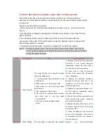
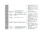
Err
03
Under voltage
The P-N voltage of the main power converter
is lower than the specified value during
servo-ON.
2) The main power line voltage is too low, an
instantaneous outage occurred, the power
source is too small, the main power is
turned off, or the main power is not fed.
3) Too small power source: the line voltage
dropped due to the inrush current at power
On.
Measure
the
terminal-to-terminal
voltages (between R, S and T).
1) Increase the capacity of the main
power or replace it with a larger one. Or
remove the causes of the failure of the
magnetic contact, and then restart the
power source.
2) Increase the capacity of the main
power. For the required capacity.
3) Correct the phase (R, S and T)
connections of the main power.
4) Check the timing of power-on (for both
the main power and control power).
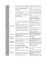
Err
04
Over heat
The radiator is heated up to exceed the limit
temperature. The power elements of the
driver are overheated. Overload.
The heat sink is heated up to exceed the
limit temperature. The power elements of
the driver are overheated. Overload.
Err
06
Encoder error
1. Encoder is damaged.
2. Encoder is not well connected with the
driver.
1. Check encoder.
2. Check wiring.
Err
07
EEPROM read /
write error
1) The data contained in the parameter
storage area of the EEPROM is broken, so
erroneous data is retrieved.
2) The check code of the EEPROM is broken,
so erroneous data is retrieved.
Set all the parameters again. If this error
occurs frequently, the driver may have
been broken. Replace the driver with a
new one. Return the old driver to the
sales agent for repair.
The driver may have been broken.
Replace the driver with a new one.
Return the old driver to the sales agent
for repair.
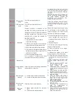
Err
08
Parameters
initiation fault
Err
09
No encoder
1
Encoder cable is not connected.
2
Encoder cable may be broken.
1
Re-connect encoder cable.
2
Check encoder cable.
Err-10
Baud rate error
The driver checked wrong baud rate setting,
and changes the setting to 57600BPS
automatically.
Reset the baud rate according to
parameter table.
Err
11
position error too
large
1) The motor velocity exceeds the specified
limit.
2) The position error pulse is larger than Pr63
(position error limit). The motor operation
does not respond to the commands.
1) Decrease the target speed (command
values).
2) Adjust the electronic gear ratio so that
the frequency of the command pulse is
500 kpps or less. If an overshoot occurs,
readjust the gains.
Correct the encoder wiring per the
wiring diagram. Check whether the motor
Содержание GA204-107
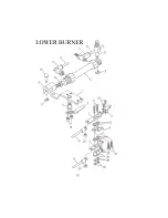
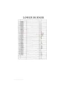
Страница 1: ...BT 11020 RP TB PARTS INSTRUCTION MANUAL...
Страница 8: ...00 1 2 3 4 5 2 50 054 5 652257 5 58 9 5 4 4 57 22 4 5 3 257...
Страница 9: ......
Страница 10: ...0 1 2 3 4 2 3 4 3 5 6 503 7 3 4 8 3 9 9 2 5 5 0 0 5 0 5 5 3...
Страница 11: ......
Страница 12: ......
Страница 13: ......
Страница 14: ......
Страница 15: ......
Страница 16: ......
Страница 17: ......
Страница 18: ......
Страница 19: ......
Страница 20: ......
Страница 21: ......
Страница 22: ......
Страница 23: ......
Страница 24: ......
Страница 25: ......
Страница 26: ......
Страница 27: ......
Страница 28: ......
Страница 29: ......
Страница 30: ......
Страница 31: ......
Страница 32: ......
Страница 33: ......
Страница 34: ......