background image


2


3.10  Inputting symmetrical pattern ....................................................................................................... 54 
3.11  Modification of the feed pitch....................................................................................................... 54 
3.12  Drawing repeat design .................................................................................................................. 55 
3.13  Deleting pattern............................................................................................................................. 56 

4  Download patterns from PC...................................................................................................................... 56 
5  Maintainance of IO Devices ..................................................................................................................... 59 

5.1 

Input devices check....................................................................................................................... 59 

5.2 

Output devices check .................................................................................................................... 59 

6  Appendix................................................................................................................................................... 61 

Appendix 1. System parameter list ........................................................................................................... 61 
Appendix 2. Trouble Indication Table ...................................................................................................... 65 
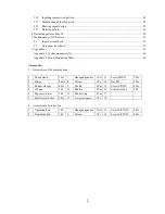
 
Accessories: 

1 Accessories of the machine head 
   

Thead stand 

1Set 

Hexagon apanner  1Set  13 

ScrewM5X12 

9Pcs 

Hinge 

2Sets  8 

Oil can 

1Pc 

14 

Nut M5 

9Pcs 

Rubber wasger 

4Pcs  9 

Needle 

5Pcs  15 

Screw St3X10 

6Pcs 

Oil pan 

1Pc 

10 

Bobbin 

5Pcs  16 

Silicon oil box 

1Pc 

Big screw driver 

1Pc 

11 

Rubber ring   

3Pcs  17 


Smsll screw dvtrer 

2Pcs  12 

Foot pedal support 

1Pc 

18 


2 Accessories of control box 

Operation box 

1PC 

Hexagon apanner  1Set  13 

Screw St6.3X30 

4Pcs 

Download line 

1Pc 

Oil can 

1Pc 

14 

Screw St4.2X30 

4Pcs 


Содержание GA204-107

Страница 1: ...BT 11020 RP TB PARTS INSTRUCTION MANUAL...

Страница 2: ...djusting zero position 34 2 2 1 Adjusting the position of the induction rion for the sensor of the needle upper position 34 2 3 Basic operation 35 2 4 Transfering patterns by a USB disk 38 2 5 Adjusti...

Страница 3: ...ation Table 65 Accessories 1 Accessories of the machine head 1 Thead stand 1Set 7 Hexagon apanner 1Set 13 ScrewM5X12 9Pcs 2 Hinge 2Sets 8 Oil can 1Pc 14 Nut M5 9Pcs 3 Rubber wasger 4Pcs 9 Needle 5Pcs...

Страница 4: ...8 45 4 4 7 91 4 4 I 7 23 3 3 28 7 JK 8 22 39 LM A 0 7 4N173 4 892 3 8 392 O 924 39 3 9 2 6 3 17 2 77 3 JK 8 22 39 LM 892 17 6 7 2 81 2 4 P 3 P 1 0 2 4 Q 4 2 1 4 2 277 2 8992 C 5 2 P 7 5 7 4 P 73 3 3 7...

Страница 5: ...44 2 86 B2 H7 4 2 42 2 67 2 6 44 D C F G 4 6 44 A2 2 B2 6 44 42 2 B B 8 F G 4 6 2 4 2 2 8 I 66 7 G 4 4 2 4 C 3 2 6 44 6 D E F G 4 42 2 8 C A2 6 4 0 12 2 3 4 6 6 4 4 2 66 2 2 4 5 C J D E F G 4 2 42 6 B...

Страница 6: ...3 4 3 2 9 4 H 4I3 0 2 9 7J 0 0 5 D2 0 5 3 6 4I3 4 92 2 0 4055 5 D 0K 0 6 4I3 0 2 63 5 3 J 43 0 L L D3 0 790 0 2 3 8 3 790 43 2 3 D2 0 5 0 40 4 2 40 5 2 M055 2 3 4 2 2 4055 N0 N0 O P 4I3 2 3 5 5 0 40...

Страница 7: ...0 1 2 0300 45 61 0300 3 3 0300 4 7 85 9 4 7 4 37 4 4 43 4 3 5 4 4 1 43 0300 4 3 0 443 4 3 13 4 4 5 A 37 0300 4 3 1 0300 1 4 B 11 4 4 3 11 5 C3 D 3 37 4 3 3 3 0300 3 1 0 E 37 FGH 37 0300 5 6 5 I...

Страница 8: ...00 1 2 3 4 5 2 50 054 5 652257 5 58 9 5 4 4 57 22 4 5 3 257...

Страница 9: ......

Страница 10: ...0 1 2 3 4 2 3 4 3 5 6 503 7 3 4 8 3 9 9 2 5 5 0 0 5 0 5 5 3...

Страница 11: ......

Страница 12: ......

Страница 13: ......

Страница 14: ......

Страница 15: ......

Страница 16: ......

Страница 17: ......

Страница 18: ......

Страница 19: ......

Страница 20: ......

Страница 21: ......

Страница 22: ......

Страница 23: ......

Страница 24: ......

Страница 25: ......

Страница 26: ......

Страница 27: ......

Страница 28: ......

Страница 29: ......

Страница 30: ......

Страница 31: ......

Страница 32: ......

Страница 33: ......

Страница 34: ......

Страница 35: ...ure detect switch 0 off 1 on Pressure testing of 0invariant 1negation Add Trim when NOP MOVE 0no 1yes pressure box up when trim 0no 1yes path of return origin 2 0 path 1 direction sweeping thread swit...

Страница 36: ...16 Thread loose open time 1 180 P 17 pressurebox width check mm 300 300 P 18 presser foot up time 50 2000 P 19 main shaft start time 40 1000 P 20 presserfoot max height 30 200 mm P 21 z sensor polarit...

Страница 37: ...ratio 600000 50000000 P 16 Y motor transmission ratio 600000 50000000 P 17 stretch presser foot up time 40 500 P 18 change the needle time 150 500 P 19 motor rotation direction 0invariant 1negation P...

Страница 38: ...specified value 1 The driver failed due to defective circuits or IGBT parts 2 Motor wires U V and W are shorted 3 Motor wires U V and W are grounded Motor burned 5 Poor connection of Motor wires 6 Th...

Страница 39: ...ck the timing of power on for both the main power and control power Err 04 Over heat The radiator is heated up to exceed the limit temperature The power elements of the driver are overheated Overload...

Страница 40: ...ase the capacity of the driver and motor Lengthen the ramp time of acceleration deceleration Reduce the motor load 2 Readjust the gains 3 Correct the motor wiring per the wiring diagrams Replace cable...

Страница 41: ...al Err 24 Motor overheating Motor overheating protector action 1 Improved motor cooling and cooling conditions 2 False alarm caused by bad contact of motor encoder line Err 25 Motor holding break abno...

Отзывы: