background image

29 


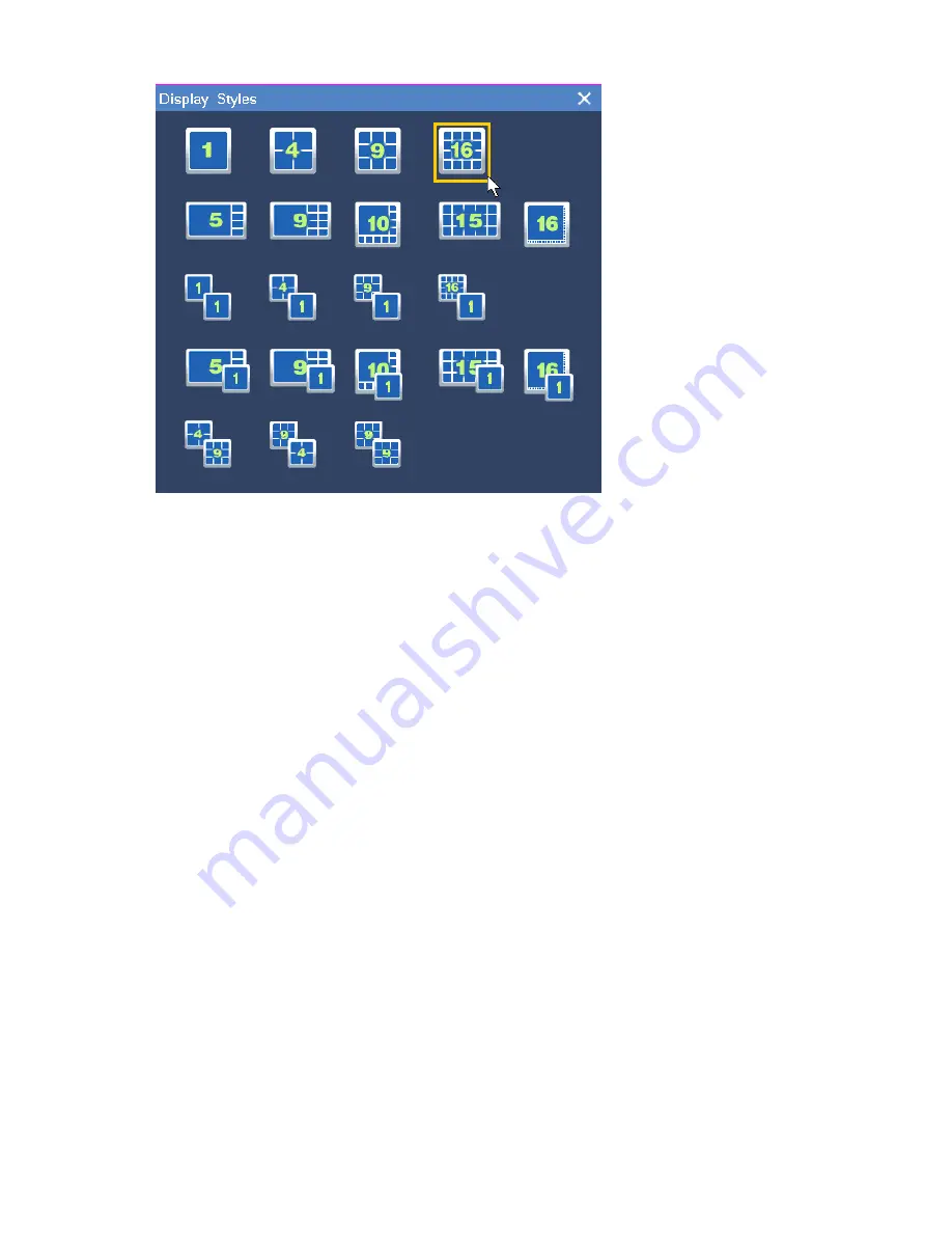
You can also set the screen layout for the secondary screen in this dialog box. 

To create a screen layout scheme with cameras bound to view windows, do as follows: 

1.  Determine a screen layout by performing the previous two steps. 

2.  Bind cameras and view windows. 

1)  Right-click a view window and choose 

Camera Choice

2)  Click the target camera.  Alternatively, click 

Discovery of new equipment

  to find the target 

camera, as shown in the following figure. 

Содержание NVR1822

Страница 1: ...I NVR1822 and NVR1825 User Guide Version 02 August 2015 ...

Страница 2: ...hts reserved Without the prior written permission of Suzhou Keda Technology Co Ltd any reproduction translation or retransmission of all or any part of this document for any purpose in either electronic or mechanical form is not allowed Notice The information in this document is subject to change without notice Every effort has been made in the preparation of this document to ensure accuracy of th...

Страница 3: ...cy Masks 23 3 6 Changing and Touring Surveillance Sites 24 3 7 Setting and Touring Screen Layouts 28 3 8 Enabling Dual Monitor Viewing 32 3 9 Setting the Video Wall 33 3 10 Changing the Image Position 34 3 11 Configuring Image Settings 34 3 12 Listening Calling and Broadcasting 35 4 Recording 37 4 1 Starting a Recording 37 4 2 Scheduling a Recording 38 4 3 Setting the Recording Policy 39 4 4 Backi...

Страница 4: ... History Alarms 56 7 Miscellaneous 58 7 1 Basic System Information 58 7 2 Querying the System Information 60 7 3 Importing or Exporting User Data 60 7 4 User Authorization 61 7 5 E Mail Notification 66 7 6 Rebooting the System 66 7 7 Shutting Down the System 66 7 8 Logging Out from the System 67 8 Specifications 68 9 Abbreviations and Acronyms 75 ...

Страница 5: ... Change Type Description Feature change Editorial change Updated screenshots Changed the document name from 1820 Series NVR User Guide to NVR1822 and NVR1825 User Guide Deleted the specifications of the NVR1821 Version 01 2014 12 12 Compared with Version 00 2014 06 30 Version 01 2014 12 12 includes the changes described in the following table Change Type Description Feature change Replaced the Aut...

Страница 6: ...ots Version 00 2014 06 30 This is a draft Compatibility The following table provides the products and NVR software version to which this document applies Product NVR1822 HD HDA NVR1825 HD HDA NVR1825 HP NVR Software Version NVR V5R1B2 ...

Страница 7: ...management system and applications NVR Station is a complete system for device management video surveillance and video recording NVR Station Web is a web based application of the NVR Station Mobile NVR Client is an iOS Andriod compatible mobile application of the NVR Station For details about the NVR appearance and specifications see chapter 8 Specifications 1 2 Key Features The following table li...

Страница 8: ...ails on how to use this feature see section 3 5 Setting Privacy Masks Image Flip This feature allows you to track an object continously as it passes beneath a camera For details on how to use this feature see section 3 3 2 Advanced PTZ Controls Playback 9 Channel 720p Video Playback A spectacular 1280 by 720 resolution lets you see more of your high resolution images with pixel for pixel accuracy ...

Страница 9: ... IP cameras Unlike standards such as the Universal Serial Bus which also powers devices over data cables PoE allows long cable lengths The following NVRs supoprt this standard NVR1825 4HP NVR1825 9HP 1 3 Major Specifications Homing From a single NVR you can view and control up to 64 cameras WDR This feature allows you to record greater scene details from shadows to highlights than normal IR Infrar...

Страница 10: ... account will be locked for 10 minutes If you forget your password contact your system administrator to retrieve the default password of your account Note The graphical user interface GUI of the NVR is continuously changed Therefore do not be alarmed when you find the screenshots in this document are different from actual ones We greatly appreciate your understanding All the screenshots in this do...

Страница 11: ... the following conditions are true The registration address of the camera is one IP address of the NVR This indicates that the camera has registered with the NVR The camera can reach the NVR This feature can also retrieve a camera that registered with the NVR but was preempted by another NVR later if the following conditions are true The camera is still on the camera list of the NVR The camera is ...

Страница 12: ...comes with your NVR IPCSearch can find cameras encoders and decoders that are located in the same broadcast domain as your personal computer PC How to use this feature To use this feature choose Main Menu Devices Auto Add as shown in the following figure ...

Страница 13: ...era For details see section 3 2 1 Adding Cameras 3 2 Manually Adding Editing Replacing and Deleting Cameras 3 2 1 Adding Cameras To manually add a camera 1 Choose Main Menu Devices Search Add 2 Select the camera from the search results and click Add Devices as shown in the following figure ...

Страница 14: ...TSP or ONVIF camera 1 Click Single point add and specify parameters displayed as shown in the following figure 2 Click OK 3 Select the camera from the search results and click Add Devices as shown in the following figure ...

Страница 15: ...cify User Name and Password as shown in the following figure If you want to add a number of ONVIF cameras that use the same user name and password select Using the same user name and password Then all these cameras can be added at a time ...

Страница 16: ...rag the camera to a view window to monitor the corresponding area 3 2 2 Editing Cameras To change the network settings of a camera 1 Choose Main Menu Devices Search Add 2 Select the camera from the search results and click Modify Address 3 Change parameter values as required 4 Click OK Note that you can change the network settings only for cameras that use the factory defaults To change the sequen...

Страница 17: ... the following figure 3 Click OK 3 2 3 Replacing Cameras To replace an existing camera with a new camera 1 Choose Main Menu Devices Search Add 2 In the displayed Search Add dialog box select the camera from the search results and click Replace as shown in the following figure ...

Страница 18: ...ced 4 Click Replace 3 2 4 Deleting Cameras To delete a camera 1 Choose Main Menu Devices 2 In the Device Management dialog box select the camera from the camera list and click Remove 3 In the Remove Devices dialog box select the camera and click Delete 4 Click Close ...

Страница 19: ...tively Adjusting the Focus Click or for near or far focus respectively Click for autofocus Camera Control Menu Click and to show enter and exit the camera control menu respectively These buttons apply only to specific cameras Turning on or off the Backlight Click or to turn on or off the backlight respectively Day and Night Mode Click or to enable or disable the day and night mode respectively Cli...

Страница 20: ...lance site and Stop Cruise to stop the patrol Rotate Image Each time you click Observe the image will be rotated 90 clockwise Each time you click Reverse the image will be rotated 90 counterclockwise Preset Position Click Save to save the current position as a preset position When the camera moves to another position you can enter a preset position in the text box and click Load to move the camera...

Страница 21: ...corresponding camera be equipped with a wiper IR Infrared camreas can capture objects when there is insufficient visible light to see This option requires that the corresponding camera support IR Auto Tilt 180 The Auto Tilt 180 feature works as follows When you press and hold to enable a camera to tilt down to the maximum tilt angle 90 it quickly pans 180 and tilts upward If you still hold the cam...

Страница 22: ...Click Hori to horizontally flip the video image 180 and Vert to vertically flip the video image 180 Zoom Speed Click Fast to accelerate the zoom speed and Normal to use the normal zoom speed Pan 180 Click Flip to enable a camera to pan 180 Restrict Pan Range The Hor_Limit option allows you to set two borders on the horizontal plane Then the camera cannot move beyond these borders To set two border...

Страница 23: ...9 Click Close Set Pan Tilt Zero With the VZ option you can create a virtual zero point the pan tilt is zero After you create a virtual zero point for a camera the camera moves to the virtual zero point upon the power on To create a virtual zero point for a camera 1 Right click the corresponding view window and choose PTZ Control 2 Select a position for the camera using and 3 Click and go to the se...

Страница 24: ...Scan Limit option restricts the patrol area for a camera Before selecting this option 1 Set two borders on the horizontal plane through Hor_Limit 2 Start a patrol though Start Cruise After you select this option the corresponding camera patrols the area with the previous borders This option requires that two borders on the horizontal plane have been configured through Hor_Limit Image Freeze The St...

Страница 25: ...mit Zooming limit Shutter Shutter speed Plus Gain White Balance Set the white balance mode Red Plus Red gain Pan Pan a camera Tilt Tilt a camera Note If you find an option does not take effect contact the camera system administrator to check whether the camera in question supports the option If so contact the local authorized Kedacom agent 3 4 e PTZ The electronic PTZ e PTZ function allows you to ...

Страница 26: ... then select privacy blocks 3 Click the button in the bottom right corner of the window and confirm your operation 4 Click Save and then Back After the preceding steps are performed you will find that masked fields turn black 3 6 Changing and Touring Surveillance Sites To change the surveillance site 1 Right click the current view window and choose Camera Choice 2 Click the target camera and then ...

Страница 27: ... the touring scheme These cameras are to be toured 4 Enter a dwell time for cameras You can enter either a unique dwell time for a camera or a unified dwell time for several cameras To enter a unique dwell time for a camera select the camera and select a time length from the Unified Waiting Time drop down list as shown in the following figure ...

Страница 28: ...nter a unified dwell time for several cameras 1 Select these cameras 2 Select the Unified Waiting Time option 3 Select a time length from the Unified Waiting Time drop down list The following is an example ...

Страница 29: ...ample 7 Click Start and then Back After the preceding steps are performed live videos from these surveillance sites are toured on the view window To tour multiple surveillance sites on a secondary screen 1 Right click a view window and choose Advance Auxiliary Sequence 2 In the displayed dialog box select a touring scheme By default the Channel Poll1 scheme is ...

Страница 30: ...r for each camera using the Up and Down buttons 6 Optional Click Rename to rename the current touring scheme 7 Click Start and then Back 3 7 Setting and Touring Screen Layouts When multiple view windows are displayed on the main screen you can set the screen layout create a screen layout scheme with cameras bound to view windows and tour screen layout schemes To set the screen layout do as follows...

Страница 31: ...meras bound to view windows do as follows 1 Determine a screen layout by performing the previous two steps 2 Bind cameras and view windows 1 Right click a view window and choose Camera Choice 2 Click the target camera Alternatively click Discovery of new equipment to find the target camera as shown in the following figure ...

Страница 32: ...3 Right click a view window and choose Layout Scheme 4 In the displayed dialog box click Get Picture Browse Plan as shown in the following figure ...

Страница 33: ... Optional Click Rename to rename the current layout scheme The following is an example 6 Click Save To tour screen layout schemes do as follows 1 Right click a view window and choose Advance Scheme Sequence ...

Страница 34: ...following is an example You can change the order for each scheme using the Up and Down buttons 3 Optional Click Rename to rename the current touring scheme The following is an example 4 Click Start and then Back 3 8 Enabling Dual Monitor Viewing Enabling the feature ...

Страница 35: ...n homologous output mode the output from the VGA and HDMI ports is the same Only the NVR1825 4HD HDA NVR1825 9HD HDA and NVR1825 4 9HP support this mode In heterologous output mode the output from the VGA and HDMI ports is different All the NVR1822 and NVR1825 variants except the NVR1825 4HD HDA and NVR1825 9HD HDA support this mode 3 9 Setting the Video Wall You can monitor sites on a video wall ...

Страница 36: ...ote If you find an option does not take effect contact the camera system administrator to check whether the camera in question supports the option If so contact the local authorized Kedacom agent 3 11 Configuring Image Settings To configure image settings for a camera 1 Right click a view window and choose Advance Video Adjustment 2 Change parameter values according to onsite conditions as shown i...

Страница 37: ...ult settings 3 Click Save 3 12 Listening Calling and Broadcasting Along with exceptional image quality the NVR can also record audio To listen to a camera 1 Right click the corresponding view window and choose Volume Control 2 Click To call a camera ...

Страница 38: ...trol 2 Select Call To start a broadcast 1 Right click the corresponding view window and choose Volume Control 2 Select Broadcast To switch from a call to a broadcast select Broadcast To switch from a broadcast to a call stop the broadcast by clicking and select Call ...

Страница 39: ...ing by setting the recording mode for a camera Method 1 Right click a view window and choose Recording Mode Enable Method 2 1 Right click a view window and choose Recording Mode Record Control Alternatively choose Main Menu Record Record Control 2 Select a camera ...

Страница 40: ...function By alarm linkage Through alarm linkage a recording can automatically start when an alarm is triggered To schedule a recording 1 Choose Main Menu Alarm Service Alarm 2 Select an alarm type from the Type drop down list for example motion detection 3 Select a source day and period 4 Click Linkage Edit 5 Select a linked camera from the Linkage Device drop down list as shown in the following f...

Страница 41: ...p down list and select a day and period If necessary click Copy and specify parameters to copy the scheduling settings to all cameras or specific cameras 3 Click Save Note This function applies only to cameras whose recording mode is Auto 4 3 Setting the Recording Policy The recording policy includes the following What to do when storage space is insufficient When a recording will be resumed after...

Страница 42: ...ccording to onsite conditions 3 Click Save 4 4 Backing Up Records To back up records 1 Choose Main Menu Record Backup 2 Optional Enter a keyword in the text box next to Select to quickly find the target camera 3 Select the target camera from the camera list 4 Select a recording date as shown in the following figure ...

Страница 43: ... data This option can accelerate the backup progress However the backups can be played back only by the nvrlocalplayer that comes with the NVR 7 Click Backup 8 In the displayed dialog box select a disk and click Backup 4 5 Querying Records To query record backups 1 Choose Main Menu Record Backup Query 2 In the Backup Query dialog box select a disk from the Disk drop down list 3 Click Search After ...

Страница 44: ...details see chapter 5 Playing Back ...

Страница 45: ...art a multi record playback 1 Choose Main Menu Record Multi Play 2 Select a layout for example the four window screen layout 3 Click one view window and select one camera from the camera list on the right panel to bind the camera and the view window together 4 Select or enter a recording date under Record Date and select a start time on the timeline ...

Страница 46: ...ted by default If you do not select a start time the earliest time point on the timeline is selected by default 5 Repeat steps 3 and 4 for each target camera 6 Click or for each view window Note that pink sections of the timeline indicate that alarms are generated during this period and that green sections of the timeline indicate that records are available during this period The following table d...

Страница 47: ...s for fast backward and fast forward Electronic PTZ Click the arrow button to draw a square to digitally zoom in Click the hand button to move the image up down left or right Right click the view window to return to the playback screen Layout Select a layout Skip Enter a start time and click the arrow to skip to the start time Exit Exit the playback window To switch to live viewing move your curso...

Страница 48: ...ect a recording date the current date is selected by default If you do not select a start time the earliest time point on the timeline is selected by default 5 Click or Method 2 1 Right click a view window and choose Record Query 2 Select a recording date under Record Date and select a start time on the timeline 3 Click or Method 3 1 On a view window click 2 Select a recording date under Record Da...

Страница 49: ...n select events to display and configure intervals for fast backward and fast forward Electronic PTZ Click the arrow button to draw a square to digitally zoom in Click the hand button to move the image up down left or right Right click the view window to return to the playback screen Cycle Repeatedly play back a certain section of a record using the Cycle button Back Up Back up a certain period of...

Страница 50: ...at records are available on this date From the view of the set theory the displayed dates are the union of the selected cameras For example records are available on March 1 for camera 1 and records are available on March 2 for camera 2 In such a case the dates March 1 and 2 are blue 5 Click each view window to check for the time points when records are available 6 On the control panel select a sta...

Страница 51: ...the NVR receives the notification After this the Alarm Moving text is displayed on the main screen Note that this feature is available only to service alarms To enable this feature for a camera 1 Right click the corresponding view window and choose Device Setting Motion Detection as shown in the following figure 2 Select Enable Motion Detection 3 Set the detection sensitivity 4 Select a detection ...

Страница 52: ...ection Setting 5 Select Enable Motion Detection as shown in the following figure 6 Set the detection sensitivity 7 Select a detection area 8 Click Save 6 2 Configuring Service Alarms To configure a service alarm do as follows 1 Choose Main Menu Alarm Service Alarm 2 In the displayed Service Alarm dialog box configure parameters as required as shown in the following figure ...

Страница 53: ...splayed together with the name of the source camera on the Current Alarm window 5 Click Detection Setting to enable the motion detection function and configure function related settings 6 Click Back 7 Select one or multiple duration options 8 Click Linkage Edit 9 In the displayed Linkage Edit dialog box choose a device to be linked for example another camera The following is an example ...

Страница 54: ...d Start a recording Caption Display the duration the alarm persists When the alarm is cleared regardless of whether manually or automatically the duration disappears Switch to Live When the one picture screen layout is selected the system displays the live video from the linked camera immediately after an alarm is generated When the live video from multiple cameras is displayed on the main screen ...

Страница 55: ...he corresponding view window and choose PTZ Control 2 Choose a location for the camera by using PTZ controls which are Up Down Left and Right 3 Click Advanced Tab 4 On the first page enter a digit in the text box next to the Preset Position parameter 5 Click Save The numbers of preset locations supported by cameras vary according to the camera type To TvWall Send the video from the linked camera t...

Страница 56: ... the alarm If the linked device is the NVR itself the actions are as follows Action Description Remarks EMail Send an alarm notification to the preset email address To configure mail settings choose Main Menu Settings Mail Service Buzzer Enable the beeper on the NVR 3 Click Save 6 3 Configuring System Alarms To configure system alarms 1 Choose Main Menu Alarm System Alarm 2 In the displayed System...

Страница 57: ...ected A device is disconnected from the NVR No Disk No storage disk is found Disk Fault A faulty storage disk is found IP Conflict An IP address of the NVR is in duplicate Net Broken The network cable is disconnected Lower Speed The network speed is low Recording Space Full No space is available for records MAC address conflict An MAC address of the NVR is in duplicate 3 Click Save ...

Страница 58: ...d when the exception or motion that triggers the alarm no longer exists The alarm persists if the exception or motion persists 6 5 Querying History Alarms To query a specific type of history alarms generated on all cameras connected to the NVR 1 Choose Main Menu Alarm History Alarm 2 Select a general alarm type for example service alarm 3 Select a service alarm type for example alarm input 4 Speci...

Страница 59: ...57 triggered Note that the recording is stopped as soon as the exception or motion that triggers the alarm no longer exists The following is an example ...

Страница 60: ... descriptions for all parameters or options displayed Parameter or Option Description Device Name Name of the NVR NVR No Number of the NVR The default value for this parameter is 8 You must enter an NVR number before you can use a monitoring keyboard to control the corresponding NVR However the NVR1822 and NVR1825 do not support monitoring keyboards System Language Display language ...

Страница 61: ...ts of multiple record units This parameter can be configured as follows 1 64 MB 2 128 MB 3 256 MB 4 512 MB 5 1024 MB 6 2048 MB Record Download Speed Rate at which records are downloaded Enable the operation password When this option is selected the password is required if you want to manage disks Setup Wizard When this option is selected the Setup Wizard is evoked every time the NVR restarts Auxil...

Страница 62: ...on of the secondary stream on an ONVIF camera 7 2 Querying the System Information Choose Main Menu Settings System Information to query the system information The following is an example 7 3 Importing or Exporting User Data Choose Main Menu Settings Import Export to import or export user data as shown in the following figure ...

Страница 63: ...ory of the USB flash drive Only the system administrator is allowed to import or export user data 7 4 User Authorization When you are authorized to manage user accounts you can add edit delete and disable standard users When you are not authorized to manage user accounts you can only query your account s user authorization information and change your account s password 7 4 1 Adding a User Account ...

Страница 64: ...played New dialog box specify parameters displayed as shown in the following figure 3 Click OK By default a standard user is allowed to perform the following operations System Recording and Capturing Configuring System Settings Managing Devices Managing Alarms Configuring Video Wall ...

Страница 65: ...ser data Managing disks and configuring IP SAN settings Switching off the system Rebooting the system 7 4 2 Editing a User Account To change the user authorization for a standard user 1 Choose Main Menu Settings User 2 Select the user from the user account list and click Right as shown in the following figure 3 Specify parameters displayed according to onsite conditions ...

Страница 66: ... Menu Settings User 2 Select the user from the user account list and click Reset Password 3 In the displayed dialog box click Yes to confirm your operation To change the password of your own account 1 Choose Main Menu Settings User 2 Select your account from the user account list and click Change Password 3 In the displayed Change Password dialog box specify parameters displayed as shown in the fo...

Страница 67: ... the displayed dialog box click Yes to confirm your operation 7 4 4 Disabling a User Account To disable a standard user for a certain period 1 Choose Main Menu Settings User 2 Select the user from the user account list and click Disable 3 In the displayed Disable User dialog box select a time length from the drop down list next to the Disable parameter 4 Click Disable ...

Страница 68: ...figure Note Parameters tagged with are mandatory 7 6 Rebooting the System To reboot the NVR 1 Choose Main Menu Shutdown Restart 2 In the displayed dialog box click Yes to confirm your operation 7 7 Shutting Down the System To shut down the system 1 Choose Main Menu Shutdown Shutdown 2 In the displayed dialog box click Yes to confirm your operation ...

Страница 69: ...67 7 8 Logging Out from the System To log out from the system 1 Choose Main Menu Shutdown User Logout 2 In the displayed dialog box click Yes to confirm your operation ...

Страница 70: ...20P XGA SVGA D1 CIF QCIF Number of disks allowed to be installed 8 4 Maximum number of view windows 16 16 Video decoding H 264 baseline main high profile Audio RCA line in and RCA line out support for bidirectional audio transmit Audio encoding and decoding Encoding ADPCM Decoding ADPCM AACLC G 711U G 711A AMR Network protocols TCP IP UDP HTTP DHCP DNS DDNS RTP RTCP RTSP PPPoE FTP SNTP VSIP Video ...

Страница 71: ...g temperature 10 C to 55 C Relative humidity 10 to 90 non condensing Atmospheric pressure 70 kPa to 106 kPa Altitude 60 m to 3000 m Size height x width x depth 88 mm x 443 mm x 461 mm Weight 6 9 kg excluding disks Connection 128 such NVRs can connect to the NVR Station The following table lists NVR1825 HD variants Front Panel Sub model NVR1825 4 9HD NVR1825 16 32HD Channel 4 9 channels each of whi...

Страница 72: ... decoding Encoding ADPCM Decoding ADPCM AACLC G 711U G 711A AMR Network protocols TCP IP UDP HTTP DHCP DNS DDNS RTP RTCP RTSP PPPoE FTP SNTP VSIP Video out 1 HDMI maximum resolution 1920 x 1080 1 VGA maximum resolution 1920 x 1080 Alarm in out Control ports Disk ports 2 SATA ports 2 SATA ports Network ports 1 RJ45 port 10Base TX 100Base T adaptive 1 RJ45 port 100Base TX 1000Base T adaptive USB por...

Страница 73: ... Sub model NVR1825 4 9HDA NVR1825 16HDA Channel 4 9 channels each of which occupies a bandwidth of 5 Mbit s 16 channels each of which occupies a bandwidth of 5 Mbit s Resolution 1080P UXGA 960P 720P XGA SVGA D1 CIF QCIF Number of disks allowed to be installed 1 1 Maximum number of view windows 9 16 Video decoding H 264 baseline main high profile Audio RCA line in and RCA line out support for bidir...

Страница 74: ...1 RJ45 port 100Base TX 1000Base T adaptive USB ports 2 USB2 0 ports 2 USB2 0 ports Power 12 V DC Operating frequency Rated power 15 W excluding disks Operating temperature 10 C to 55 C Relative humidity 10 to 90 non condensing Atmospheric pressure 70 kPa to 106 kPa Altitude 60 m to 3000 m Size height x width x depth 40 mm x 350 mm x 240 mm Weight 1 6 kg excluding disks Connection 128 such NVRs can...

Страница 75: ... support for bidirectional audio transmit Audio encoding and decoding Encoding ADPCM Decoding ADPCM AACLC G 711U G 711A AMR Network protocols TCP IP UDP HTTP DHCP DNS DDNS RTP RTCP RTSP PPPoE FTP SNTP VSIP Video out 1 HDMI maximum resolution 1920 x 1080 1 VGA maximum resolution 1920 x 1080 Alarm in out 2 alarm inputs and 2 alarm outputs Control ports 1 RS485 Disk ports 2 SATA ports Network ports 1...

Страница 76: ... 10 C to 55 C Relative humidity 10 to 90 non condensing Atmospheric pressure 70 kPa to 106 kPa Altitude 60 m to 3000 m Size height x width x depth 40 mm x 350 mm x 240 mm Weight 1 6 kg excluding disks Connection 128 such NVRs can connect to the NVR Station ...

Страница 77: ...bbreviations and Acronyms ANR automatic network replenishment NVR Network Video Recorder ONVIF Open Network Video Interface Forum OSD on screen display RTSP Real Time Streaming Protocol WDR wide dynamic range ...

Отзывы: