background image

Instructions for use KaVoLUX 540 LED U / T

8 Safety check - Test instructions | 8.1 Mounting the device

92 / 110

8 Safety check - Test instructions

8.1 Mounting the device

Note

The test instructions for the KaVoLUX 540 LED U / T to be mounted to
devices are described in the instructions for use of the respective treatment
unit
The measurement of the protective earth, defined in the instructions for use
for the relevant treatment unit, must be extended to include the measuring
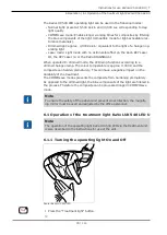
points "Scan the light head of the treatment light KaVoLUX 540 LED with the
probe".

See also:

2

8.2.2.2.4.2 Scan the light head of the treatment light KaVoLUX 540 LED
with the probe, Page 101

8.2 Ceiling mounting

Note

This chapter describes the safety check performed on the
KaVoLUX 540 LED T for the case of ceiling mounting.

8.2.1 Introduction

General instructions

Note

The safety check may only be carried out by one or more electricians (as
defined in IEC 61140) who have been appropriately trained for the device to
be inspected.

Note

The contents and specified tests described in this document are based on the
international standard, IEC 62353. This standard applies to the testing and
inspections of medical electrical devices or medical electrical systems comply-
ing with IEC 60601-1 (DIN EN 60601-1).

Note

In order to evaluate the safety of medical devices, systems or components of
medical devices or systems, the safety check must be carried out at the fol-
lowing times:

Prior to startup

during servicing

during inspections and maintenance

following repairs

on the occasion of recurrent tests

Содержание LUX 540 LED U

Страница 1: ...Instructions for use KaVoLUX 540 LED U T ...

Страница 2: ...Distributed by KaVo Dental GmbH Bismarckring 39 D 88400 Biberach Phone 49 0 7351 56 0 Fax 49 0 7351 56 1488 Manufacturer Kaltenbach Voigt GmbH Bismarckring 39 D 88400 Biberach www kavo com ...

Страница 3: ...urpose Proper use 14 3 2 Operating light KaVoLUX 540 LED U 16 3 3 Operating light KaVoLUX 540 LED T 17 3 4 Dimensions and swing range 17 3 5 Rating plates 19 3 6 Technical data and requirements 20 3 7 Overview of use 21 3 8 Accessories 22 4 Assembly 23 4 1 Packaging 23 4 1 1 Transportation and storage 23 4 1 2 Packed items 23 4 1 3 Removal from the packaging 25 4 2 Requirements for mounting 27 4 2...

Страница 4: ...84 6 2 Operation of the treatment light KaVoLUX 540 LED T 84 6 2 1 Turning the operating light On and Off 85 6 2 2 Setting the brightness 85 6 2 3 Changing between COMPOsave mode res dimmed light and normal light 86 6 2 4 Switch on COMPOsave mode 86 6 2 5 Setting the brightness of the dimmer 87 6 2 6 Set colour temperature 87 6 2 7 Turning the laser mode On and Off 87 6 2 8 Operation of the 3D joi...

Страница 5: ...ty 105 10 3Guidelines and manufacturer s statement Electromagnetic immunity 106 10 4Recommended protective clearances between portable and mobile HF telecommunication devices and the KaVoLUX 540 LED 108 Instructions for use KaVoLUX 540 LED U T Table of contents 5 110 ...

Страница 6: ...Assembly instructions TI Technician s instructions IEC International Electrotechnical Commission RI Repair instructions RK Retrofitting kit AS Assembly kit CK Conversion kit EP Enclosed parts EMC Electromagnetic compatibility PI Processing instructions 1 1 2 Symbols See the Safety Warning Symbols section Important information for users and technicians CE mark according to Medical Devices Directive...

Страница 7: ... be held liable for defects and their consequences due to natural wear improper cleaning or servicing non compliance with operating servicing or connection instructions calcification or corrosion contaminated air or water supplies or chemical or electrical factors deemed abnormal or impermissible in accordance with factory specifications The warranty does not usually cover bulbs glassware rubber p...

Страница 8: ... tioned obligations will mean that the damage will be considered to have arisen following delivery in accordance with the General German Freight For warders Terms and Conditions Art 28 Outside Germany Note KaVo shall not be held liable for damage arising from transportation The shipment must be checked on arrival If the packaging is visibly damaged on delivery please proceed as follows 1 The recip...

Страница 9: ...ase keep the packaging in case you need to return the product for servi cing or repair The symbols printed on the outside are for transportation and storage and have the following meaning Transport upright with the arrows pointing upwards Fragile protect against impact Protect from moisture Permissible stacking load Temperature range Humidity Air pressure 9 110 ...

Страница 10: ...on of hazardous steps The warning and safety notes in this document must be observed to prevent personal injury and material damage The warning notes are designated as shown below DANGER In cases which if not prevented directly lead to death or severe in jury WARNING In cases which if not prevented can lead to death or severe injury CAUTION In cases which if not prevented could lead to minor or mo...

Страница 11: ... KaVoLUX 540 LED This is an optical illusion that makes the handpiece appear to be standing still or rotating extremely slowly Risk of injury If the stroboscopic effect is evident change the speed slightly and continue working as usual CAUTION Premature hardening of composite fillings A light intensity that is too high can have a negative impact on the durability of the treatment Select the approp...

Страница 12: ...ved when the KaVoLUX 540 LED T is mounted to a treatment center The electrical installation must comply with the requirements and guidelines set down in VDE 0100 710 The safety checks must be done at 24 month intervals See also 2 8 Safety check Test instructions Page 92 2 3 Disposal Note Any waste which is generated must be recycled or disposed of in strict com pliance with all applicable national...

Страница 13: ...oceed as follows 1 On the homepage www enretec de of enretec GmbH you can download a form for a disposal order under the menu item eom Download the disposal order or complete it as an online order 2 Enter the corresponding information to complete the order and submit it as an online order or by fax 49 0 3304 3919 590 to enretec GmbH The following contact options are also available for questions an...

Страница 14: ...an be mounted to the following treatment units ESTETICA E80 E80 Vision ESTETICA E70 E70 Vision ESTETICA E50 E50 Life The KaVoLUX 540 LED T can be mounted in the following positions to the fol lowing treatment centres on the ceiling Primus 1058 1058 Life Status 1080 Globus 1078 ESTETICA Sensus 1066 ESTETICA Comfort 1065 ESTETICA Standard 1063 ESTETICA E30 DSEclinical CENTRO support system Proper us...

Страница 15: ...t accident prevention regulations Regular servicing and safety checks are essential for the permanent assurance of the operating and functional safety of the KaVo product and for the preven tion of damage and hazards Testing and maintenance intervals Maintenance must be performed once a year the safety checks at intervals of 2 years Shorter intervals for the safety checks may be specified by the t...

Страница 16: ...LUX 540 LED U Note The KaVoLUX 540 LED U operating light is only suitable for mounting to the KaVo treatment centre ESTETICA E80 E70 E50 and E50 Life as it can be directly controlled via the treatment centre Components of the KaVoLUX 540 LED U Mounting pole Swivel arm Spring arm 3D joint Handles Mirror optional Operating light head ...

Страница 17: ... ESTETICA Standard 1063 ESTETICA E30 as well as for mounting to DSEclinical dental simulation units The assembly kit Mat no 07243401 is required for installation Components of the KaVoLUX 540 LED U Operating light head Handles 3D joint Control panel Spring arm Swivel arm Ceiling mounting kit Mat no 1 008 8406 Mirror optional 3 4 Dimensions and swing range CAUTION Collision with persons or pieces o...

Страница 18: ...VoLUX 540 LED U T 3 Product description 3 4 Dimensions and swing range 18 110 843 659 120 240 300 Dimensions in mm 763 843 659 131 1 3 1 1 3 1 1 3 1 45 3 2 0 3 0 3 0 3 0 3 0 3 2 0 118 140 140 17 1 7 2 8 45 Swing ranges in mm ...

Страница 19: ...acture month serial number Supply voltage and power Reference number to product HIBC Code Type description VDE mark Disposal instructions see intended use eLabeling ID CE mark Read and take note of the content of accompanying documents The rating plate of the ceiling mounting kit is fastened to the ceiling Rating plate KaVoLUX 540 LED T ceiling installation Device type Material number Year of manu...

Страница 20: ...ith DIN VDE 0100 710 Free end at assembly point 1000 mm Customer provided fuse protection Automat C 16 or screw plug fuse 10 A Can be connected to the auto matic unit of the dental treatment centre Main fuse of the terminal T 500mA H 250 V Colour reproduction and illumination strength Colour temperature normal light ca 4 000 to 6 000 Kelvin preset 5 500 Kelvin daylight quality Colour rendering ind...

Страница 21: ...se Operating light Use Treatment centre Material number KaVoLUX 540 LED U R Right hander units ESTETICA E70 E80 Vis ion ESTETICA E50 Life 1 008 7973 KaVoLUX 540 LED U L Left hander units ESTETICA E70 E80 Vis ion ESTETICA E50 Life 1 008 7974 KaVoLUX 540 LED U R Centro Assembly on Centro with right hander units ESTETICA E70 E80 Vis ion ESTETICA E50 Life 1 008 8323 KaVoLUX 540 LED T R Right hander un...

Страница 22: ...ion for KaVo units or third party units 1 009 4273 KaVoLUX 540 LED T R L ceiling mounting Right hander left hander units for ceiling mount ing Device independent sup plement office configur ation for KaVo units or third party units 1 009 1430 xx technically possible but KaVo recommends the KaVoLUX 540 LED U version 3 8 Accessories Mat No Material summary 1 009 4132 Mirror for KaVoLUX 540 LED 1 002...

Страница 23: ... 6 Air pressure 700 hPa to 1060 hPa 4 1 2 Packed items For device assembly Packaged item Operating light with accessories and mounting pole Length 975 mm Width 545 mm Height 370 mm Gross weight approx 18 4 kg Net weight approx 13 4 kg For ceiling mounting for ceilings up to 2 7 m high 1 packed item Operating light with accessories ceiling adapter and stay bar Length 1 100 mm Width 600 mm Height 47...

Страница 24: ...D U T 4 Assembly 4 1 Packaging 24 110 Length 1 100 mm Width 600 mm Height 470 mm Gross weight approx 25 kg Net weight approx 18 kg 2 Stay bar Length 930 1300 mm Width 280 mm Height 230 mm Gross weight approx 13 kg Net weight approx 10 kg ...

Страница 25: ...rating light from damage when it is being removed from the pack aging and during installation Do not loosen the cable tie until the swivel arm has been installed The following sequence must be observed for the removal from the packaging Remove the Styrofoam filling from the treatment light 1 1 1 4 2 3 Grasp the treatment light by the cluster and by the spring arm and re move upwards and vertically...

Страница 26: ... the operating light into the mounting pole Do not loosen the cable tie until the swivel arm has been installed Do not remove the protective sheath until the swivel arm has been in stalled See also 2 4 3 1 2 Install the swivel arm Page 31 2 4 3 2 2 Install the swivel arm Page 34 ...

Страница 27: ...e protective earth conductor Take the anchor plate from the accessories and fix into place with the en closed screws Attach the cover and lock by turning clockwise 4 2 2 Requirements for mounting the device Note Comply with the provisions of IEC 601 Turn off the main switch before mounting The assembly of the device KaVoLUX 540 LED comprises the following steps in the specified sequence Install th...

Страница 28: ...er the ceiling mounting set and stay bar are automatically included in the delivery Note When noting the ceiling height in the order please indicate if the ceiling is suspended 4 3 Assembly of the KaVoLUX 540 LED U 4 3 1 ESTETICA E50 E50 Life WARNING Electrical power Death or injury from electric shock Before servicing pull the mains plug out of the socket or completely discon nect the device from...

Страница 29: ... LED U Removing the rear service flap Remove the cover of the connection point Unscrew the cover Loosen screw below the main switch Loosen the fastening screws of the cladding see arrow and remove the cladding Loosen screws on the disinfection container and remove the container 29 110 ...

Страница 30: ...onto the mounting pole Insert the mounting pole into the lamp holder Positioning the mounting pole It is approx 1680 mm from the top edge to the floor The borehole for the swivel arm brake points in the direction 6 o clock Tighten the earth protector screw and fastening screws and Return the disinfection container to its former position and fix with screws Align the body of the unit so that the mo...

Страница 31: ...ough the lamp mounting pole Support arm with operating light and spring arm to be inserted in the lamp mounting pole from the top Screw in screw Mat no 10091123 to backstop ð The support arm must be able to rotate approx 270 Screw in brake and adjust to the required braking force Connect the lines Screw the earth protector to the earth terminal Route the control and supply cables through the unit ...

Страница 32: ...rm the safety check according to the treatment centre Mount the device covers 4 3 2 ESTETICA E70 ESTETICA E80 WARNING Electrical power Death or injury from electric shock Before servicing pull the mains plug out of the socket or completely discon nect the device from the power to de energise it After conversion check the electrical safety according to DIN EN 62353 IEC 62353 ...

Страница 33: ...Instructions for use KaVoLUX 540 LED U T 4 Assembly 4 3 Assembly of the KaVoLUX 540 LED U Install the mounting pole 33 110 ...

Страница 34: ...for the brake points to 6 o clock position 6 o clock position corresponds to the direc tion of the main switch of the unit Fix the mounting pole with locking screws and PE screw Guide the cover ring on the unit body as far as it will go Note The paint may be damaged if the mounting pole slips into the lamp holder Firmly hold the mounting pole when you insert it Make sure not to crush any cables In...

Страница 35: ...l PCB Setting the CAN terminating resistance Note The CAN terminating resistances must be set correctly to ensure faultless functioning of the ESTETICA E70 and E80 The setting is dependent on the configuration of the device There are two CAN circuits the CAN circuit device and the CAN circuit patient chair in every treatment unit The circuits can be set independently of each other After the instal...

Страница 36: ... S5 S5 SW1 S2 E80 SN 100xxxxx without 540 LED on off off off on n a with 540 LED off off off off on fix on E70 SN 200xxxxx without 540 LED n a on off off on n a with 540 LED n a off off off on fix on not available nicht vorhanden with Display Memospeed on the assistant element this switch must be set to on CAN bus device Unit control Dentist control KaVoLUX 540 LED Switch S5 E70 SN 201xxxxx E80 SN...

Страница 37: ...SW200 SW200 SW200 S2 E80 all SN with mot headrest off on off off on without mot headrest on on off off n a E70 all SN with mot headrest off on n a n a on without mot headrest on on n a n a n a not available nicht vorhanden Final tasks Mount caps on the swinging and spring arm Run function test Perform the safety check according to the treatment centre Mount the device covers 4 3 3 ESTETICA E70 E80...

Страница 38: ... U 38 110 Installing the light mounting pole Note The holder for the lamp mounting pole is not a top stop for the lamp mounting pole Note The lamp mounting pole must be adjusted together with the monitor or the panorama x ray viewer so that the handle does not shear off the tumbler filler ...

Страница 39: ...ock position corresponds to the direc tion of the main switch of the unit Adjust the mounting pole to the corresponding height and fix with locking screws and PE screw Guide the cover ring on the unit body up to the end stop Note The paint may be damaged if the mounting pole slips into the lamp holder Firmly hold the mounting pole when you insert it Make sure not to crush any cables Install the sw...

Страница 40: ...nd plug into the slot on the central control PCB X12 1 Final tasks Mount caps on the swinging and spring arm Run function test Perform the safety check according to the treatment centre Mount the device covers Note The KaVoLUX 540 LED U operating light is recognised automatically by the E70 E80 Vision treatment centre No further settings need to be made on the treatment centre ...

Страница 41: ... Unit V2 3 0 Dentist V2 1 3 Display Dentist V2 3 0 E70 From 201xxxxx Unit V2 3 0 Dentist V1 5 0 E80 100xxxxx Unit V2 3 0 Dentist V2 1 3 Display Assist Dentist V2 3 0 E80 From 101xxxxx Unit V2 3 0 Dentist V1 5 0 KaVoLUX 540 LED V1 2 1 If necessary carry out the firmware update See also 2 TI of the respective treatment centre ESTETICA E50 E50 Life ESTETICA E70 from SN 20100000 and ESTETICA E80 from ...

Страница 42: ...til U04 is shown on the display Press button S3 to raise the index to 9 Press the S5 button to set the note bit to 0 ð OP light LED is shown on the display Press and hold down button function level to quit the service mode Press the Remote Control button ESTETICA E70 from SN 20100000 and E80 from SN 10100000 Note The note bit OP light LED must be set to 1 in service mode U04 Index 28 to activate t...

Страница 43: ...d to make adjust ments in service mode Service tester Service tester I C Mat no 1 003 2212 See also 2 TA treatment unit Start continue and end the service mode To start service mode press and hold the Decrease value and Increase value keys Press the foot pedal ð Service mode U1 is displayed Press the Select level button until U04 is shown on the display Press the Increase value button and the Redu...

Страница 44: ...nue and end the service mode Press and hold down the Timer menu and Patient menu keys Press MEMOdent menu key briefly ð Press the Instrument menus button until U04 is shown on the display Function keys Description S2 Increase index S3 Reduce index S4 Index set 0 S5 Set delete flag bit Press button S2 or S3 to raise the index to 28 or to reduce the index Press the S5 button to set the note bit to 1...

Страница 45: ...nt chair must be moved downwards to install the operating light Press button left and right on the foot control simultaneously and press down the cross switch to move the patient chair downwards 1 6 3 4 1 5 2 If the fastening screws penetrate the mount lift the cover and turn the screws back Pick up the insertion tool at the receiver tube and push through the lamp mounting pole Insert the lamp mou...

Страница 46: ...ssembly of the KaVoLUX 540 LED T 46 110 Put the washer onto the lamp mounting pole 3 2 1 Thread the cover over the lamp mounting pole Connect the supply cable and protective conductor using the insertion tool and pull completely through the lamp mounting pole ...

Страница 47: ...erating lamp into the lamp mounting pole Connect the protective conductor Connect supply lines to the terminals and pack in tubing as displayed Seal both ends of the tubing tightly with cable ties Pull back the lines ensuring that the connection terminals with the shrink tubing remain in the support arm of the unit 47 110 ...

Страница 48: ...imedia opening of the lamp mounting pole 2 1 Then push the lines in small loops through the multimedia opening in the lamp mounting pole again Turn the swivel arm of the lamp until the threads appears behind the holes 1 Screw the brake and backstop into the lamp mounting pole Connect the lines Insert the cable of the operating light into the cable holder and connect it at X24 0V and 24V ...

Страница 49: ...erform the safety check according to the treatment centre Mount the device covers 4 4 2 Primus 1058 WARNING Electrical power Death or injury from electric shock Before servicing pull the mains plug out of the socket or completely discon nect the device from the power to de energise it After conversion check the electrical safety according to DIN EN 62353 IEC 62353 49 110 ...

Страница 50: ...ssembly of the KaVoLUX 540 LED T 50 110 Install the mounting pole Remove the unit covers 1 Loosen screws on the disinfection container and remove the container Ensure that the protective earth screw and fastening screws and do not reach into the light holder ...

Страница 51: ...ontainer to its former position and fix with screws Align the body of the unit so that the mounting pole is exactly vertical see device installation instructions Check with a spirit level Push down the cover ring on the mounting pole Install the swinging arm See also 2 4 3 1 2 Install the swivel arm Page 31 Connect the lines Run the protective conductor and connect it to the body base 8 Manual ope...

Страница 52: ...tions of the treat ment centre The operating light is connected via the DCA relay Note ERGOcom light may not be connected to the DCA relay X28 if this connec tion is possible ERGOcom light will be damaged otherwise Connect cable to terminal strip 24 V AC Connect cable to DCA relay slot 12 Route a wire jumper from the DCA relay slot 13 to terminal strip 0 V AC ...

Страница 53: ...Instructions for use KaVoLUX 540 LED U T 4 Assembly 4 4 Assembly of the KaVoLUX 540 LED T 1 2 3 6 5 4 X28 KaVoLUX 540 LED T KaVoLUX 540 LED T 53 110 ...

Страница 54: ...WARNING Electrical power Death or injury from electric shock Before servicing pull the mains plug out of the socket or completely discon nect the device from the power to de energise it After conversion check the electrical safety according to DIN EN 62353 IEC 62353 Install the mounting pole Pivot the rear panel outward on the bottom and pull the lugs out in downward direction 1 2 Unscrew the scre...

Страница 55: ...LED U T 4 Assembly 4 4 Assembly of the KaVoLUX 540 LED T Lift the hood and take it off towards the front 1 2 3 Unscrew the screws Dismantle the side panels 2 1 Loosen screws on the disinfection container and remove the container 55 110 ...

Страница 56: ...onto the mounting pole Insert the mounting pole into the lamp holder Positioning the mounting pole It is approx 1680 mm from the top edge to the floor The borehole for the swivel arm brake points in the direction 6 o clock Tighten the earth protector screw and fastening screws and Return the disinfection container to its former position and fix with screws Align the body of the unit so that the mo...

Страница 57: ...he lamp mounting pole Support arm with operating light and spring arm to be inserted in the lamp mounting pole from the top Screw in screw Mat no 10091123 to backstop ð The support arm must be able to rotate approx 270 Screw in brake and adjust to the required braking force Connect the lines Screw the earth protector to the earth terminal Route the supply cables through the unit to the central con...

Страница 58: ...4 4 ESTETICA Standard 1063 Comfort 1065 Sensus 1066 WARNING Electrical power Death or injury from electric shock Before servicing pull the mains plug out of the socket or completely discon nect the device from the power to de energise it After conversion check the electrical safety according to DIN EN 62353 IEC 62353 Install the mounting pole Mounting rod for ESTETICA Standard 1063 1065 1066 Mat n...

Страница 59: ... ESTETICA Standard 1063 Comfort 1065 Sensus 1066 the lamp support Mat no 07404711 is not mounted as a standard and must be fitted subsequently Insert the lamp support Mat no 07404711 into the support for the top of the stand and tighten with screws 2 3 4 Slide the cover ring Mat no 07105822 over the mounting pole 59 110 ...

Страница 60: ...r Positioning the mounting pole It is approx 1680 mm from the top edge to the floor The borehole for the swivel arm brake points in the direction 6 o clock Fix the mounting rod with the clamping screw 5 6 7 With the aid of the screws align the mounting rod so that is standing ex actly vertically spirit level Install the swinging arm See also 2 4 3 1 2 Install the swivel arm Page 31 Connect the lin...

Страница 61: ...afety check according to the treatment centre Mount the device covers 4 4 5 Globus 1078 S Status 1080 TM C WARNING Electrical power Death or injury from electric shock Before servicing pull the mains plug out of the socket or completely discon nect the device from the power to de energise it After conversion check the electrical safety according to DIN EN 62353 IEC 62353 Install the mounting pole ...

Страница 62: ...oor The borehole for the swivel arm brake points in the direction 6 o clock Tighten the protective conductor screw and fixing screws Align the mounting pole see unit installation instructions so that it is pre cisely vertical use a spirit level Install the swinging arm See also 2 4 3 1 2 Install the swivel arm Page 31 Connect the lines Connect the protective conductor to the body of the unit Conne...

Страница 63: ...embly 4 4 Assembly of the KaVoLUX 540 LED T Contact 2 blue wire Black wire is free X14 Final tasks Mount caps on the swinging and spring arm Run function test Perform the safety check according to the treatment centre Mount the device covers 63 110 ...

Страница 64: ... Install the stay bar Connecting the lines Affix the covers Mount the ceiling adapter Determine the location on the ceiling for attachment according to installa tion plan Mat no 3 000 2059 included in the delivery of the ceiling mounting kit Adhere the self adhesive drilling template to the ceiling mounting site so that the arrow is facing 6 o clock Die Lage des InstallationsrohrsfŸr die elektrisc...

Страница 65: ...rs and nuts on the thread of the back of the anchor 2 3 4 Screw the nuts tight so that the anchors grip the masonry Remove the nuts and washers Position the adapter base plate in such a way that the arrow is point ing 6 o clock and secure with washers and nuts Completely screw locknuts onto the grub screws 65 110 ...

Страница 66: ...stay bar to the correct length see installation plan Mat no 3 000 2059 Guide the large cover over the stay bar Turn the brass ring of the stay bar in a clockwise direction Position the swivel arm on the stay bar in such a way that the cover points to the stay bar and the retaining pin can be inserted into the des ignated borehole Fasten the swinging arm to the stay bar with 4 screws Guide the line...

Страница 67: ...Instructions for use KaVoLUX 540 LED U T 4 Assembly 4 5 Ceiling assembly of the KaVoLUX 540 LED T 5 6 7 1 2 3 4 67 110 ...

Страница 68: ... and mains cable through the borehole and through the stay bar until only the five core end of the mains cable is protruding from the borehole 8 9 Connect the protective conductor of the mains cable and the supplementary protective conductor to to the front of the swivel arm Connect the supplementary protective conductor to the ceiling adapter above ...

Страница 69: ...ix with screws Mat no 0 261 5031 and plate nut Mat no 1 004 5511 Insert the litz wires according to the connection diagram on the back of the switch Line No Switch No 1 1 1A 1A 2 2 2A 2A Carefully snap in the switch and cover into the swinging arm hole and screw the cover tight with the screws Install the stay bar Mount the intermediate plate of the stay bar with the elongated slots and to the gru...

Страница 70: ...ew and tighten all the hex head nuts Adjust the nuts on the grub screws in the ceiling adapter so that the stay bar is suspended exactly perpendicular with the floor use a spirit level Connecting the lines Note Only a certified electrician may install the electrical system Follow the provisions set down in VDE 0100 710 for the electrical installation Note It must be ensured that the mains cable pr...

Страница 71: ...ing light to the terminal U KaVoLUX 540 the polarity is irrelevant Roll up excess lengths of the lines and clamp them with a cable tie Affix the covers Note When the ceilings are covered use cover Mat no 07405992 Remove the stud bolts from the small cover and pull the cover down Affix the large cover to the small one with the stud bolt so that the stud bolt points 6 O Clock and shove it upward 71 ...

Страница 72: ...to position and lock the small cover with the three stud bolts 4 6 Centro mounting of the KaVoLUX 540 LED To be able to mount the KaVoLUX 540 LED on the Centro stand the routing of the lines in the swivel arm of the light needs to be changed 1 2 3 Cut off the cable tie fixing the lines to the aluminium insert of the swivel arm ...

Страница 73: ... LED Remove the 4 Phillips head screws and pull the aluminium insert out of the swivel arm Route the lines over the aluminium insert and pass them through the hole downwards Remount the aluminium insert Fix the lines with a cable tie ð Now the light can be mounted to the Centro stand 73 110 ...

Страница 74: ...se with which the swinging arm rotates Rotate the swinging arm until the screw is visible under the hole Tighten the screw to make it more difficult to rotate the swinging arm or loosen it to make it easier 5 2 Set the spring arm brake Note Use the brake to set the smooth running of the spring arm rotation Loosen and remove the cover in an anti clockwise direction Use the brake screw to set the sm...

Страница 75: ...e set using different brakes 5 3 1 Setting the rotary motion und 3D joint movement Note The cover must be removed to set the rotary motion and the 3D tilting The cover is fastened with a snap lock and can be removed without tools Take off cover Use the adjusting screw to set the smooth running of the rotary motion Unlock the 3Dm joint movement on the regulating ring 75 110 ...

Страница 76: ...t using two brakes Brake is for the presetting and needn t be adjusted in normal cases To set the brake the cover must be removed The cover is fastened with a snap lock and can be removed without tools Brake is used for the precision adjustment and can be set without the cover having to be removed The adjustment can be carried out by the med ical staff Presetting Release cover and remove from the ...

Страница 77: ... Mechanical settings 5 3 Setting the light head brakes Fine adjustment Pivot the light head upwards until the orifice in the cover of the cross slot adjustment screw is visible Carry out the precision adjustment with the adjustment screw 77 110 ...

Страница 78: ... field at patients users or and third parties while you switch on the light Do not direct the light field at the patient s eyes when you move the light head Maintain a clearance of approx 700 mm between the operating light and the mouth of the patient CAUTION Stroboscopic effect of the rotating instrument A stroboscopic effect could arise in instruments rotating at a certain speed dur ing applicat...

Страница 79: ...amp functions according to a dimmed halogen lamp The colour temperature is approx 4 000 K and the composite can harden prematurely This can have a negative impact on the durability of the treatment The COMPOsave modes prevents the composite from hardening prematurely As opposed to the dimmed light the blue components of the light are filtered in the process Therefore the composite can be processed...

Страница 80: ...ight key Press and hold down the Treatment light key ð Signal buzzes brightness changes from dark to bright in stages When the desired brightness is reached release the Treatment light key 6 1 3 Changing between COMPOsave mode res dimmed light and normal light Press and hold down the switch of the foot control and press the Dim treat ment light button until you hear the buzzer ð The treatment ligh...

Страница 81: ...g prematurely As opposed to the dimmed light the blue components of the light are filtered in the process Therefore the composite can be processed longer in COMPOsave mode Note Use the Dim operating light button to activate the COMPOsave mode The light can be dimmed in COMPOsave mode Sensor KaVoLUX 540 LED Press the Dim treatment light key or Hold your hand in front of the sensor for 2 sec ð The C...

Страница 82: ...ton 6 1 6 Set colour temperature Note The colour temperature of the treatment light KaVoLUX 540 LED U can be set between five stages with the X ray viewer button in operating mode Treat ment lamp on The visual perception of the teeth can be adapted or en hanced by changing the colour temperature 4 000 to 4 500 Kelvin similarity to halogen light 5 500 Kelvin daylight quality Press and hold down the...

Страница 83: ...neously on the dentist element of the treatment unit ð The laser mode switches on ð Laser mode is activated the operating light shines for 1 second in green and then changes to a white light ð The indicator diodes of the two buttons flash alternatively or Hold your hand in front of the sensor for 3 sec ð The laser mode switches on ð Laser mode is activated the operating light switches initially in...

Страница 84: ...n be rotated 45 to the left or 45 to the right Turn the switching ring to the right and it will spring back to its original pos ition ð If the treatment light is turned to the centre position zero position it will automatically lock into place in the centre position 6 2 Operation of the treatment light KaVoLUX 540 LED T Control panel KaVoLUX 540 LED T Treatment lamp key Treatment lamp dimming key ...

Страница 85: ...LUX 540 LED Press the operating light button or Hold your hand just in front of the sensor ð Treatment light is switched on Press the operating light button once again or Hold your hand just in front of the sensor ð Treatment light is switched off 6 2 2 Setting the brightness Note The maximum possible brightness of the light is set in five steps using the Treatment light key Press and hold down th...

Страница 86: ...tions according to a dimmed halogen lamp The colour temperature is approx 4 000 K and the composite can harden prematurely This can have a negative impact on the durability of the treatment The COMPOsave modes prevents the composite from hardening prematurely As opposed to the dimmed light the blue components of the light are filtered in the process Therefore the composite can be processed longer ...

Страница 87: ...radiation in tensity Press and hold down the Dim operating light button ð Brightness is increased in five stages Release the Dim operating light button when the desired brightness is achieved 6 2 6 Set colour temperature Note The colour temperature of the treatment light KaVoLUX 540 LED T can be is set between five stages with the Mode Colour temperature button The visual perception of the teeth c...

Страница 88: ...e KaVo KEY Laser III the KEY Laser 3 or the KaVo DIAGNOdent Sensor KaVoLUX 540 LED Press the operating light button and the operating light dimming button on the operating light simultaneously ð The laser mode switches on ð Laser mode is activated the operating light shines for 1 second in green and then changes to a white light or Hold your hand in front of the sensor for 3 sec ð The laser mode s...

Страница 89: ...e switching ring to the left until it snaps into place ð Treatment light can be rotated 45 to the left or 45 to the right Turn the switching ring to the right and it will spring back to its original pos ition ð If the treatment light is turned to the centre position zero position it will automatically lock into place in the centre position 89 110 ...

Страница 90: ...has cooled down CAUTION Damage to product as a result of improper cleaning Malfunctions unclean surfaces and risk of infection for operator and patients When using detergents adhere to the manufacturer s instructions CAUTION Damage to product as a result of improper disinfection Malfunctions When using disinfectants adhere to the manufacturer s instructions When disinfecting wipe only Do not immer...

Страница 91: ...no 10024489 with a disinfectant wipe or thermodisinfection slight discolouration possible Approved disinfectants Incidin Liquid Ecolab FD 322 Dürr Microcide AF Liquid Schülke Mayr Use disinfectants in accordance with the Instructions for Use of the manu facturer See also 2 Disinfectant material safety data sheet Snap the handles on again 7 4 Sterilisation 7 4 1 Sterilising the handles Note The whi...

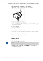
Страница 92: ...ote This chapter describes the safety check performed on the KaVoLUX 540 LED T for the case of ceiling mounting 8 2 1 Introduction General instructions Note The safety check may only be carried out by one or more electricians as defined in IEC 61140 who have been appropriately trained for the device to be inspected Note The contents and specified tests described in this document are based on the i...

Страница 93: ...ontained in the instructions for use must be adhered to in all products to be tested and inspected Note KaVo offers a medical device book for keeping an inventory and recording es sential master data on the medical device The medical device book is only available in German Mat no 0 789 0480 Note The following tests and measurements must be documented for example in the medical device book We recom...

Страница 94: ...ce are interconnected via data lines or otherwise e g via electrically conductive attachments or coolant tubes the earth wire resistance of every single device must be checked Note If it should be impossible to check single ME devices that are functionally connected to an ME system individually for technical reasons the ME system must be checked as a whole Components of the safety check Visual ins...

Страница 95: ...measuring processes The measured values may not over shoot the specified values Note Comparisons with previous measurements must be carried out if the meas ured values undershoot the threshold values by more than 10 The test in tervals should be reduced if a deterioration in values is determined 8 2 2 Instructions for the safety check Visual inspection Check the following items in advance Has the ...

Страница 96: ...y irregularities determined in the visual inspection must be recorded in the test protocol It is essential to determine whether defects and deficiencies could have an adverse impact on the safe operation of the unit If the de termined irregularities present a safety hazard and cannot be rectified dir ectly the unit must be closed down until safe operation is restored Measurements WARNING Danger to...

Страница 97: ...arth connections could lead to erroneous measurements Note Cables and wires e g power supply cords measuring circuits and data lines must be arranged appropriately such that their influence on measurements is minimised Note The following measuring aids can be ordered KaVo measuring cable Mat no 0 411 8811 Using the measuring cable the unit is disconnected from the mains supply and connection of th...

Страница 98: ...ctor X2 of the measuring line Mat no 0 411 8811 Plug the second connector X2 of the KaVo measuring line into the mains plate X2 Insert the protective contact plug of the KaVo measuring cable into the sight window Connecting the safety tester to the treatment centre without a KaVo measuring cable Switch L N of the on site power supply cord to be voltage free Disconnect L N at the terminal Connect t...

Страница 99: ...e they leave the factory and included in the test Measuring the protective conductor resistance Limit 0 3 Ω maximum value Note The integrity of the power supply cable in particular the protective earth wire of the power cable must be ensured As this is a fixed installation the evalu ation can be conducted by means of a visual inspection If damage is determ ined the further procedure to be taken is...

Страница 100: ...ctions 8 2 Ceiling mounting 100 110 Protective earth measurement Scan the ceiling adapter of the treatment light with the probe 2 3 Base plate for the ceiling adapter Surroundings of the protective con ductor connector Surroundings of the protective con nector terminal ...

Страница 101: ... Protection class 1 WARNING Electrical power Death or injury from electric shock Conduct test for leakage current in devices of Protection Class 1 only after the protective earth test has been passed WARNING Electrical power Death or injury from electric shock Prior to connecting the treatment centre to the safety tester disconnect the treatment centre from the mains supply network Functional test...

Страница 102: ...ng results of functional tests Measuring test equipment including SN test equipment number and cal ibration period Final evaluation Name date and signature of test engineer There is a copy of a test report template at the end of the chapter on Safety Checks KaVo recommends the use of this template Note Following testing repair or adjustment it must be verified whether the ME equipment or ME system...

Страница 103: ...KaVoLUX 540 LED U T 8 Safety check Test instructions 8 2 Ceiling mounting 8 2 3 Test protocol for the safety check Unit leakage current replacement measurement Leakage current of applied part replacement measurement 103 110 ...

Страница 104: ...ecked by an authorised technician Operating light can no longer be operated via the control panel of the treatment centre Defective As an alternative operate the operating light via sensor or control buttons KaVoLUX 540 LED T Have the device checked by an authorised technician Limited sensor func tioning Contamination of the glass cover Clean the glass cover Damage to the glass cover scratches cra...

Страница 105: ... 540 LED is suitable for use in all equipment including devices in living areas and suit able for equipment which is dir ectly connected to a public power supply that also supplies build ings used for residential pur poses Transmission of voltage fluctu ation Flicker according to IEC 61000 3 3 Class A The KaVoLUX 540 LED is suitable for use in all equipment including devices in living areas and su...

Страница 106: ...pital en vironment Voltage interruptions short term interruptions and fluctuations of the supply voltage according to IEC 61000 4 11 5 V 95 inter ruption of the V T for period 40 V 60 drop in V T for 5 periods 70 V 30 drop in V T for 25 periods 5 V 95 drop in V T for 5 s 250 periods 5 V 95 inter ruption of the V T for period 40 V 60 drop in V T for 5 periods 70 V 30 drop in V T for 25 periods 5 V ...

Страница 107: ...ite check e d Disturbance is possible in the ambience of devices that exhibit the following icons Comment 1 At 80 MHz and 800 MHz the higher frequency range applies Comment 2 These guidelines may not be applicable in all situations The spread of electro magnetic waves is absorbed and reflected by buildings objects and people a The ISM frequency bands for industrial scientific and medical applicati...

Страница 108: ...of the KaVoLUX 540 LED can help to prevent electromagnetic interference by maintaining the minimum clearance between portable and mobile HF telecom munication devices transmitters and the KaVoLUX 540 LED depending on the output as defined below The table shows the necessary safe distance d depending on the transmission frequency in metres Rated power of the transmitter in Watts 150 kHz through 80 ...

Страница 109: ......

Страница 110: ...1 008 8651 Fk 20190603 12 en ...

Отзывы: