Instructions for use KaVoLUX 540 LED U / T
4 Assembly | 4.4 Assembly of the KaVoLUX 540 LED T
Note
When the mounting rod extends into the light holder, it can damage the
paint.
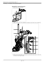
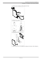
Screw in the depth stop screw
⑧
completely.
▶
Slide the cover ring
①
onto the mounting pole
②
.
▶
Insert the mounting pole into the lamp holder.
Positioning the mounting pole:
▪ It is approx. 1680 mm from the top edge to the floor
▪ The borehole for the swivel arm brake points in the direction 6 o´ clock
▶
Tighten the earth protector screw
⑥
and fastening screws
⑤
and
⑦
.
▶
Return the disinfection container
④
to its former position and fix with
screws
③
.
▶
Align the body of the unit so that the mounting pole is exactly vertical (see
device installation instructions).
Check with a spirit level.
▶
Push down the cover ring on the mounting pole.
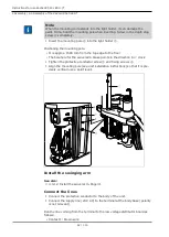
Install the swinging arm
See also:
2
4.3.1.2 Install the swivel arm, Page 31
Connect the lines
▶
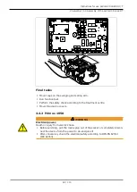
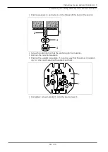
Run the protective conductor
⑧
and connect it to the body base.
8
Manual operation of the operating light via the film keypad of the
KaVoLUX 540 LED T:
The operating light is directly connected to the terminal strip.
Note
This connection must be selected when the DCA relay is already taken (for
example by the ERGOcom light).
▶
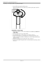
Connect the cables
⑨
and
⑩
to the terminal strip 24 V AC and 0 V AC (po-
larity is not relevant).
51 / 110
Содержание LUX 540 LED U
Страница 1: ...Instructions for use KaVoLUX 540 LED U T ...
Страница 109: ......
Страница 110: ...1 008 8651 Fk 20190603 12 en ...


