


2 – 3 HP J SERIES FOUNTAIN
MANUAL
884168 / 2021.1.1
8
3�
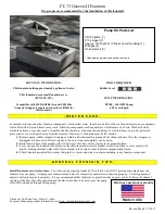
On the underside of the float, start threading the (3) 3/8 – 16 x 1/2’’ serrated hex head screws (I), but do not tighten down at this
time�
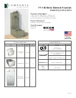
4�
Lift the unit and slide the bottom float screen (H) over the can and up to the bottom of the float, allowing the unit power cord to exit
between them in the dedicated channel�
Dedicated power
cord channel
Fig. 10-11
Fig. 12-13
Back to Contents