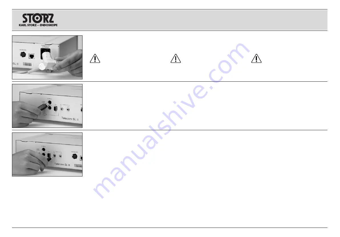
Monitor anschließen
Kamera-Kontrolleinheit mit Monitor verbinden. Je
nach Anschlussmöglichkeit ihres Monitors kön-
nen Sie die Verbindung herstellen über
– BNC-Anschluss
T
oder
– S-Video
(Y/C)-Anschluss
Y
oder
–
DV-Anschluss
U
.
Connecting the monitor
Connect the camera control unit to the video
monitor to be used. Depending upon the types of
video input connectors provided on the video
monitor, this connection can be generated using
either the CCU’s
–
BNC video output connector
T
or
–
S-Video (Y/C) video output connector
Y
, or its
–
DV video output connector
U
.
12
Conexión a la red de alimentación
Conecte el cable, introduzca el enchufe de la red
hasta el tope en el conector de la red
P
.
Cuidado:
Conecte o desconecte el
enchufe de la red de la alimentación de
corriente únicamente en sectores que no
estén expuestos a peligro de explosión.
Installation and
operating instructions
Aufstellen und
Bedienungshinweise
Montaje e
instrucciones operativas
Gerät an das Stromnetz anschließen
Netzkabel anschließen, Netzstecker bis zum
Anschlag in die Netzbuchse
P
einschieben.
Warnung:
Netzstecker nur außerhalb
explosionsgefährdeter Bereiche mit der
Stromversorgung verbinden bzw.
trennen.
Connecting power
Connect power cord. Insert power cord into
power cord receptacle
P
as far as it will go.
Warning:
Only insert the power plug into
and remove it from electrical outlets
located outside areas subject to explo-
sion hazards.
Conexión del monitor
Conecte la unidad de control de la cámara con
el monitor. De acuerdo con las alternativas de
conexión que ofrezca su monitor, la misma podrá
efectuarse sobre:
– conexión
BNC
T
ó
– conexión
S-Video
(Y/C)
Y
ó
–
conexión DV
U
.
Fußschalter anschließen
Mittels des optional erhältlichen Fußschalters
20
0101 30 mit Adapterkabel
20
2330 70 kann zwi-
schen der Standbild-Funktion, d. h. „Einfrieren“
des Videobildes auf dem Bildschirm und der
Livebild-Funktion umgeschaltet werden. Dazu
den Stecker des Fußschalterkabels in die ACC1-
Buchse
I
einstecken. Zusätzlich ist im
Benut-
zermenü
(siehe Übersicht S. 25) „Zubehör 1“ auf
„Fusspedal“ zu programmieren.
Funktion auslösen
Durch Drücken des Fußschalters wird das Video-
bild “Eingefroren”. “Für Livebild Kopftasten/ Fuß-
schalter drücken” erscheint auf dem Monitor.
Durch nochmaliges Drücken des Fußschalters
wird das Livebild wieder angezeigt.
Hinweis:
Die Umschaltung zwischen Standbild
und Livebild kann auch durch die Kamerakopf-
tasten erfolgen, falls einer der Kamerakopftasten
darauf programmiert wurde.
Connecting the footswitch
The optional footswitch
20
0101 30 and adaptor
cable
20
2330 70 may be used to toggle between
the Freeze function, i.e. the ‘frozen’ video image
on screen, and the live image function. To do
this, plug the footswitch cable into the ACC 1
socket
I
and configure Accessory 1 to
footswitch in the
User Menu
(see overview on
page 26).
Activating the function
Freeze the video image by pressing down the
footswitch. ‘Press head button/footswitch to
unfreeze’ will appear on the monitor.
Return to the live image by pressing down the
footswitch again.
Note:
You can also toggle between the still
image and live image using the camera head
buttons, if one of the buttons has been config-
ured for this purpose.
Conexión del interruptor de pedal
El uso del interruptor de pedal
20
0101 30 con
cable adaptador
20
2330 70, suministrables
opcionalmente, permite conmutar entre la fun-
ción de imagen fija, es decir, “congelamiento” de
la imagen de vídeo en la pantalla, y la función de
imagen en vivo. Para ello, introduzca el enchufe
del cable del interruptor de pedal en el conector
ACC 1
I
. Además, en el Menú de usuario (véa-
se sinopsis en la pág. 27) debe programarse
“Interruptor de pedal” en “Accesorios 1”.
Activar la función
Al presionar el interruptor de pedal, la imagen de
vídeo se “congela”. En el monitor aparece: “Para
imagen en vivo presione los botones del cabe-
zal/el interruptor de pedal”.
Presionando nuevamente el interruptor de pedal
vuelve a aparecer la imagen en vivo.
Nota:
La conmutación entre imagen fija e ima-
gen en vivo puede realizarse también utilizando
los botones del cabezal de la cámara, siempre
que uno de ellos se haya programado al efecto.
Содержание 202130 20
Страница 1: ...TELECAM SL II TELECAM SL II TELECAM SL II 202130 20 202130 20 202130 20 ...
Страница 2: ......
Страница 86: ......
Страница 89: ......
Страница 91: ......


