background image

Nesis III — Installation Manual

4.1

GNSS Signal Check

4.1

GNSS Signal Check

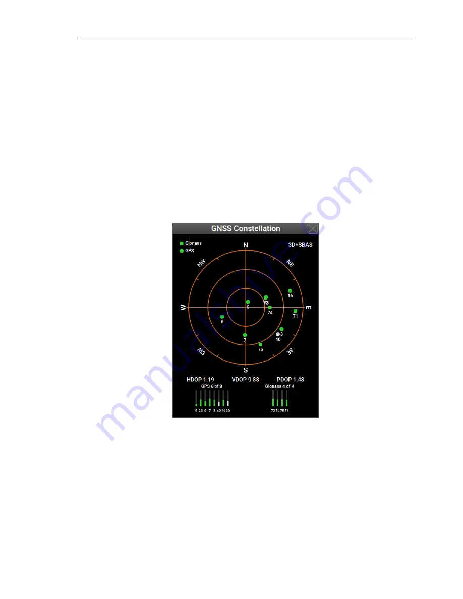
Nesis can show the GNSS satellite constellation and quality of the reception.
This is accessible under the

Info

icon.

1. Select

Options

on the main menu.

2. Select the

Info

icon.

3. Search for the

GNSS details

item and select it. A window like shown

on the Figure 14 will appear.

Figure 14:

An example of GPS and Glonass constellations. The satellite distri-
bution shows poor reception as most satellites appear in SE quad-
rant.

The window shows positions of the satellites on the sky. GPS constellation
is represented with disks and Glonass is represented with squares. All de-
tected positions are shown. Green color indicates satellites used in position
calculation. Grey color means that a satellite is being tracked, but it is not
being used in solution. Under unobstructed sky, satellites should be evenly
distributed.

23

©

Kanardia

2018

Содержание Nesis III

Страница 1: ...Nesis III Installation Manual Kanardia d o o January 2019 Kanardia d o o...

Страница 2: ......

Страница 3: ...y sa 3 0 In short the license gives you right to copy reproduce and modify this document if you cite Kanardia d o o as the author of the original work you distribute the resulting work only under the...

Страница 4: ...Nesis III Installation Manual Rev Date Description 1 0 Jan 2019 Complete manual rework 4 Kanardia 2018...

Страница 5: ...15 2 4 2 Fixation with Self Clinching Nut 15 2 4 3 Fixation with Threaded Rivet Nut Insert 16 2 4 4 Fixation with Spacer Stud and Epoxy 17 3 Power Installation 18 3 1 Circuit Breaker 19 3 2 Aircraft...

Страница 6: ...inal Communication 35 9 2 Port 1 Auxiliary RS 232 36 9 3 Autopilot Disengage 37 9 4 Alarm Switch 37 10 RS 232 Ports 38 10 1 Pinout 39 10 2 Configuration 39 10 3 Connection Details 41 10 3 1 TQ KRT2 Ra...

Страница 7: ...p 59 11 9 Restore 60 12 AHRS Leveling 60 12 1 Yaw Misalignment 61 12 2 Roll and Pitch Adjustment 62 12 3 Initial Pitch 62 13 Engine 62 13 1 Engine Model 63 13 2 Switch Function 63 13 3 Channels 64 13...

Страница 8: ...llation Manual CONTENTS 16 Autopilot 75 17 Special 75 18 CAN Devices 76 18 1 Indu Layout Change 76 18 2 Enable Disable Magnetic Heading 76 19 Joyu 77 19 1 Device Action Pairs 77 19 2 Configuration 78...

Страница 9: ...A few icons appear on the side of the manual which have special meanings This icon denotes information that needs to be taken with special attention An injury or even death is possible if instruction...

Страница 10: ...ual starts with the installation instructions for the minimal system and then adds separate sections for optional components Some components have their own installation manuals 2 Display Installation...

Страница 11: ...imensions The display main dimensions are shown on Figures 1 3 and Figure 4 shows the cutout The knob and part of the bezel protrude 23 4 mm in front of the instrument panel On the back side the housi...

Страница 12: ...nuts You can replace screws and nuts with more appropriate ones Do not use screws with head larger than 5 5 mm in diameter Do not re drill holes in the bezel Due to highly sensitive multi point touch...

Страница 13: ...ure 3 Nesis top view is necessary because some printers or PDF rendering software may slightly adjust the document size producing wrong cut out dimensions If possible make a cutout with a CNC equipmen...

Страница 14: ...9 2 6 1 6 Figure 4 Nesis cutout dimensions The figure is not actual size 2 4 Mounting Procedure Once the appropriate opening is made in the instrument panel test mount the display Adjust the opening i...

Страница 15: ...do not use excessive force on M3 bolt nut to avoid damage of plastic bezel This fixation principle has one disadvantage it makes Nesis service removal a bit difficult as nut on the back side may be di...

Страница 16: ...t Threaded rivet nut inserts a k a rivnuts may be also used especially on the composite and thin panels Again they come in various forms Some special riveting tool is needed to fix the threaded rivet...

Страница 17: ...andpaper If spacer is coated the coat shall be removed A dremel tool comes handy 2 Sand the back side of the panel where epoxy will be applied Surface must be dull 3 Mix a small batch of epoxy togethe...

Страница 18: ...ed to the power 12V or 24V terminal The blue wire connects to the ground terminal The other side of the power cable has a plastic connector This connector has a hook next to the red cable Insert the c...

Страница 19: ...e make sure that aircraft master relay in fact all relays have a protection diode a flyback diode 1 which protects against voltage spikes A coil in relays without this diode may cause spikes that exce...

Страница 20: ...plied instead of black ones The electronics part of the UPSU is shown on the Figure 11 1 2 3 4 5 6 7 Figure 11 UPSU electronics Input power leads from system bus and backup battery are on the left an...

Страница 21: ...parts the GNSS module and GNSS antenna The module is an integral part of the AD AHRS GNSS device which is built in the Nesis and the antenna cable connects to the back side of the Nesis Standard SMA m...

Страница 22: ...for antennas placed under the instrument panel covers made of thin fiberglass This does not work with metal of carbon fiber covers Nesis comes equipped with one of the two possible antennas as shown o...

Страница 23: ...gure 14 An example of GPS and Glonass constellations The satellite distri bution shows poor reception as most satellites appear in SE quad rant The window shows positions of the satellites on the sky...

Страница 24: ...ld be good See also DOP 3D SBAS 3D position is further enhanced with the SBAS system DOP Rating Description 1 Ideal Highest possible confidence level 1 2 Excellent Positional measurements are consider...

Страница 25: ...probe 1 Locate a spot in the aircraft taking into account the considerations from above and drill a 8 mm hole 2 Remove the external nut from the probe but keep the washer internal nut and plastic ins...

Страница 26: ...tion of the OAT pins 5 2 Connection The digital thermometer in the tip of the probe is type DS18B20 OAT connector is standard RJ12 type as shown on Figure 16 Description of individual pins is given in...

Страница 27: ...tion Audio output from the Nesis is 1 5 V 600 peak to peak Output is isolated with an audio transformer so both signal and ground must be connected Use of shielded cable for connection is preferred We...

Страница 28: ...io to Trig TY91 TY92 radio station 6 1 2 Funke ATR833 Audio output of the Nesis must be connected to the external audio input on Funke ATR833 radio station Please connect Nesis audio output as on Figu...

Страница 29: ...able audio input permanently and there will be always some small noise present in a headset 6 1 3 Dittel KRT2 Audio output of the Nesis must be connected to the External NF input on KRT2 radio station...

Страница 30: ...eak to peak The video signal source must be connected to Nesis with 75 coaxial cable Nesis does not recognize video format automatically In order to configure the format used by video camera follow ne...

Страница 31: ...e stick and inserting it back again usually solves the problem If the problem persist try with a memory stick made by a different producer or try to insert it into the back port 7 2 WiFi Module When a...

Страница 32: ...entation on how to enable the tethering mode Usually the procedure is as follows 1 Connect Nesis and smart phone with a USB cable 2 On the smart phone select the settings icon 3 Then select the connec...

Страница 33: ...A A 1 8 1 8 8 1 Figure 22 Designation of the CAN bus pins Pin Description 1 2 3 12V 4 CAN low 5 CAN high 6 7 8 GND Ground Table 4 Description of the CAN bus pins Our CAN bus system is running at 500...

Страница 34: ...u and Magu devices are a bit special They usually appear on each end of the main bus They have a built in 120 resistor which is used as a CAN bus terminator This means no extra terminator is required...

Страница 35: ...rminator is nothing but a simple 120 resistor between CAN high and CAN low leads pins 4 and 5 on Figure 22 and Table 4 A standard 1 4 Watt resistor will do 9 Service Port The service port consists of...

Страница 36: ...on of the service port pins one stop bit Figure 28 illustrates the connection A communication with a terminal shall be used only during production and factory maintenance or repair 1 5 6 9 GND Ter TX...

Страница 37: ...the circuit is open When the button is pressed it closes the circuit and connects pin 1 with the ground This is detected by Nesis which immediately sends the disconnect command to the servos 9 4 Alarm...

Страница 38: ...d by optocoupler and coil in the relay get is energized This in turn activates the relay switch and closes the load circuit 1 5 6 9 8 Alarm 12V 12 V Relay and yback diode Load Optocoupler inside Figur...

Страница 39: ...figure 27 illustrates pin ordering on connector and plug In most cases only pins 1 2 and 3 are connected Pin 6 is used only when you use Nesis as a power source Please note that output power on pin 6...

Страница 40: ...em Figure 34 illustrated the window 5 Select the port where device was connected and choose one of the op tions described next 6 Close all windows Nesis will reboot and new communication with device s...

Страница 41: ...s for specific devices These are merely our recommendations Some devices can be connected in different ways Any device manual always supersedes instructions given here 10 3 1 TQ KRT2 Radio Please read...

Страница 42: ...n of ATR 833 and Nesis Illustration shows only leads required by Nesis Much more leads are connected to the 25 D SUB connector Use an adapter board if possible Please refer to the ATR 833 documentatio...

Страница 43: ...ead the TRT800H Installation Manual before any connection is made to Nesis The manual can be obtained from https www funkeavionics de Open the Service menu and search for the manual Funke transponder...

Страница 44: ...TT22 Transponder Please read the TT21 TT22 Installation Manual before any connection is made to Nesis The manual can be obtained from https trig avionics com Open the Support menu and search for the m...

Страница 45: ...set KTX2 to 9600 data rate Figure 40 shows connection schematics The D SUB 15 connector on the transponder side is multipurpose connector Only connection related to the Nesis are shown Although the c...

Страница 46: ...RJ12 connector The schematics on Figue 41 shows meaning of individual pins and proper connection 6 or 8 pin flat cable can be used Pins 1 and 8 on the Flarm side can be left open as well as pins 3 and...

Страница 47: ...everal ports the schematics on Figure 42 shows two cables comming out of the main connector The bottom one connects to Nesis serial port while to top cable is optional and can be connected to one of t...

Страница 48: ...for details We recommend the configuration as shown on next figures Figure 43 shows the general page If you have a transponder on your aircraft enter the transponder ICAO address into the ICAO Mode S...

Страница 49: ...play Figure 45 TRX 1500 port 3 settings page Port is connected to Nesis 10 3 9 AIR Traffic AT1 Please read the AIR Traffic Installation Manual before any connection is made to Nesis The manual can be...

Страница 50: ...1 on AT1 with pin 1 on RJ12 However pin 6 on RJ12 and one of GND pins on AT1 shall be connected 26 19 10 18 9 1 AIR Tra c AT1 26 pin D SUB26 HD 1 12 V 2 3 4 RX 5 TX 6 GND 1 V in 12 13 TXD3 4 RXD3 22 E...

Страница 51: ...he RS 232 data port section Figure 48 shows settings we used 1 Change the RS 232 data port 3 Output to FLARM PROTOCOL and 2 change the RS 232 data port 3 RS 232 Data Rate to 57600 3 You can also exper...

Страница 52: ...to Nesis The manual can be obtained from the http www lxnavigation com web site Flarm Eagle is the smallest and lightest of all Flarm devices that we were testing Please note that ADS B in is offered...

Страница 53: ...nly affect Nesis behaviour and outlook 11 1 Layout The Layout command opens a window where Nesis screens layout is organized Figure 50 illustrates the window Several options are given Load layout is u...

Страница 54: ...ee user manual User section about aircraft designation Classic right is referred to bottom right panel on the classic screen It can show one of the following combinations Fuel computer with current an...

Страница 55: ...hers is used to send parameter values from this Nesis to other units devices connected to the CAN bus At the time of writing only Nesis and Aetos devices benefit from this feature This may eliminate t...

Страница 56: ...ion defines reaction of on parameter change The value if given is seconds A small filter value means that parameter value changes quickly while a large filter value does the opposite Please note that...

Страница 57: ...adds a new color band at the end The Color until items are added until full scale range is defined A Color until item can be also removed or inserted A valid parameter requires at least two Color unti...

Страница 58: ...are connected and properly configured with Daqu Nesis can also show their position In order to properly detect a trim position change an approximate time if travel from one trim stop to the opposite t...

Страница 59: ...B memory stick It effectively stores all major settings The saved files can be used to transfer the same settings to a different instrument or to restore settings on an existing one A valid USB memory...

Страница 60: ...ons 3 4 and above 12 AHRS Leveling During the assembly of the AD AHRS GNSS unit AIRU into the primary Nesis and during the installation of the Nesis display into the instrument panel a small misalignm...

Страница 61: ...Nesis installations are rotated regarding the air plane x axis longitudinal axis In this case the misalignment angle must be measured and its value entered into Nesis Figure 56 defines positive and ne...

Страница 62: ...ally needed when cruising speed has been changed Once the Nesis shuts down this in flight adjustment is forgotten The Initial Pitch option from Figure 55 allows entering the initial pitch cor rection...

Страница 63: ...normally used with Lycomming Continental Some ECU base engines provide fuel flow information For all others a fuel flow sensor is recommended even where such a software fuel flow model exists 13 2 Swi...

Страница 64: ...This defines the RPM limits that must be reached to automatically disengage the start button switch 13 3 Channels Nesis lists all channels available on Daqu Each channel can be configure and set accor...

Страница 65: ...window depends on the channel type and also on the selected function and sensor Bottom part of the window changes dynamically but the first four items are the same for all channels Figure 59 shows an...

Страница 66: ...propeller RPM will be shown instead of the engine RPM This value is typically set to 1 0 which results in engine RPM Figure 60 shows another example In this case an oil pressure sensor is con nected...

Страница 67: ...is connected to the channel 13 3 2 Min Max Functions like trim position flap position and throttle positions require two additional parameters After defining basic channel parameters these two parame...

Страница 68: ...ce sensor value is stable sensor value is copied to Nose Then it is trimmed fully backward and once sensor value is stable it is copied to the Tail 13 3 3 Offset For certain sensors offset can be adju...

Страница 69: ...e is assumed and only min and max value are needed 2 User up to 20 tank points can be given to define the shape 3 Predefined shapes nominal curves are predefined and the selected curve will be scaled...

Страница 70: ...s is not beneficial In order to define a user shape for tank set the Shape parameter to User The window will change slightly Then select the Edit item This opens a window where tank measurements are m...

Страница 71: ...ring measurement calibration point can be edited quantity and sensor values can be adjusted Also points can be deleted Simply click on a mea surement point and select appropriate action Figure 67a sho...

Страница 72: ...es is suitable for the cases where the shape of tank is known in advance and only Empty Full procedure must be applied This is similar to the Linear case This work well when fuel sensor mounting posit...

Страница 73: ...tank simulation is used when no fuel level sensors were config ured Selection of the Tank icon opens a simple window which accepts the fuel tank capacity Figure 69 shows situation for the 80 liters f...

Страница 74: ...ltimeter shows is too low decrease the correction For example Nesis shows 15 feet too high regarding to reference al timeter Increase correction for about 15 2 7 6 steps 0 6 hPa Dynamic airspeed allow...

Страница 75: ...djust the CO indication so that it will show about 0 ppm Note that some populated and polluted surroundings may have significant amount of CO in the air Normal values in clean environment are up to 2...

Страница 76: ...e files with the isb file extension found on the USB memory stick Select the file from the list it will be probably only one The file will be transferred to the flash memory on the selected Indu devic...

Страница 77: ...action pair can be assigned to one of Joyu buttons or Joyu wheel Devices are identified by their serial numbers This makes it possible to distinguish between devices of the same type connected to one...

Страница 78: ...ted CAN bus devices Nesis detects which devices are present on the bus and allows actions for these devices too Figure 71 shows an example of Joyu without any functions assigned Illus tration on the r...

Страница 79: ...quals to wheel An example of final situation is shown on Figure 74 When the window is closed the configuration is sent to all devices on the CAN bus They receive a complete command action list and rem...

Страница 80: ...Nesis III Installation Manual 19 2 Configuration Figure 74 Final situation three different devices are commanded with one Joyu 80 Kanardia 2018...

Отзывы: