


7.2
ECU CAN Bus Connection
miniDaqu — Manual
miniDaqu
AUXBOX
MAP
6
x
E
G
T
6
xC
H
T
6
x
A
U
X
CAN
ECU A
Baro pressure
1
2
0
R
TPS, MAT, OilP, OilT, FuelP
ECU B
Baro pressure
1
2
0
R
TPS, MAT, OilP, OilT, FuelP
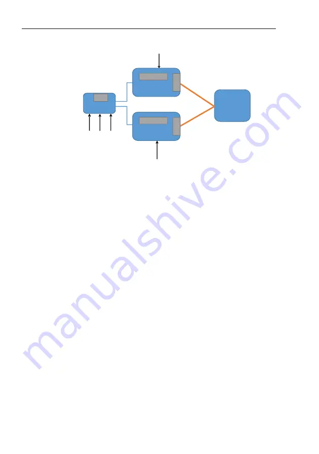
Figure 21:
Block view of dual ECU connection CAN bus.
temperature, oil pressure, oil temperature, fuel pressure, fuel flow, ECU tem-
perature, ECU supply voltage, engine hours, ignition status and sensor status.
Optional AUX box provides the following additional parameters: manifold
pressure, EGT 1-6, CHT 1-6 and some auxilary values.
Daqu can utilize all parameters provided by ECU and AUX box with exemp-
tion of auxilary values.
Please note that some additional sensors can be connected to Daqu, too.
7.2
ECU CAN Bus Connection
Please note that GND is not connected to prevent ground-loops. We assumed
that the engine and Daqu are both connected to the common aircraft ground.
The CAN connection differs regarding the number of ECUs used.
7.2.1
One ECU
When only one ECU is used, a terminator resistor must be also installed on
Daqu side (usually inside the DB9 connector between pins 4 and 8). In the
connector, which we provide, the resistor in not installed by default. You have
to install it yourself. Please refer to table 4 for correct connection of Daqu to
ULPower ECU.
©
Kanardia
2019-2022
30
Содержание miniDaqu
Страница 1: ...miniDaqu Engine Management System Manual Kanardia d o o June 2022 Revision 1 4...
Страница 2: ......
Страница 6: ...miniDaqu Manual Kanardia 2019 2022 4...