INSTRUCTION MANUAL
WIFI ENABLED MODULAR CONTROLLER
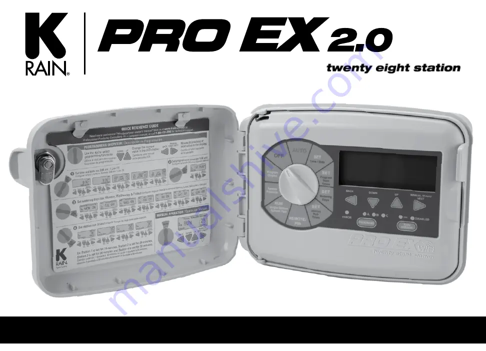
Страница 1: ...INSTRUCTION MANUAL WIFI ENABLED MODULAR CONTROLLER ...
Страница 2: ...oto RF Module Installed in Controller and optional Long Range Antenna Controls and Touch Pad 03 Setting the Controller to Off 04 Set Controller to Run Automatically 04 Program Select Button 04 Rain Sensor Select Button 05 Programming 05 u Set Time Date 06 u Set Program Start Times 06 u Set Watering Days 07 u Set Custom Operation 07 any day of the week u Set Odd Even Operation 07 calendar day u Set...
Страница 3: ...Hub Used to allow setting controller special features SPECIAL FEATURES Used to run single stations or system test cycles RUN MANUAL START NEXT BUTTON Used to start a selected irrigation program manually or to manually advance watering from one station valve to the next ERROR ALARM LED Turns on when one of the following occurs Watering is suspended by a sensor The controller senses a valve short ci...
Страница 4: ...d program the day of the week and the time of day The controller will turn on automatically to meet ANY programmed water schedules If the controller has been turned OFF via iOS Android or web browser the display will show BYPASS WiFi Simply turn the dial to OFF then back to AUTO to make the controller run in AUTO mode The PRO EX 2 0 controller has three separate programs A B and C Multiple program...
Страница 5: ...ically changes The flashing value within the display can be increased or decreased by pressing the DOWN or UP buttons To go back or advance to the next value press the BACK or NEXT buttons Because of variations in plant watering needs the PRO EX 2 0 controller has three separate programming options A B and C Each program is completely independent of each other and the controller will automatically...
Страница 6: ...be flashing in the display 10 Press the DOWN or UP buttons to set the current year 11 Return the dial to AUTO NOTE The PRO EX 2 0 controller can be set for either 12 or 24 hour display Pressing the BACK and NEXT buttons SIMULTANEOUSLY will allow user to toggle between 12 or 24 hour display The PRO EX 2 0 controller will allow up to four separate watering start times for each program 1 Use the PROG...
Страница 7: ...select the program A B or C you wish to assign watering days 2 Turn the dial to SET WATERING DAYS MON ON should appear in the display 3 Press the DOWN or UP buttons to enable ON or disable OFF day of the week operation 4 Press the NEXT button to advance to the next day of the week Repeat steps 3 and 4 until all days of the week have been set 5 Return the dial to AUTO 1 Use the PROGRAM SELECT BUTTO...
Страница 8: ...ments The remaining five hours can be set in ten minute increments 1 Use the PROGRAM SELECT BUTTON to select the program A B or C you wish to assign a run time 2 Turn the dial to SET STATION RUN TIMES The display will show all available stations module must be installed The first available station num ber will be flashing 3 Press the DOWN or UP buttons to set the number of seconds minutes hours yo...
Страница 9: ...Manual operation can be canceled anytime by turning the dial to OFF for 3 seconds 6 Return the dial to AUTO NOTE Pressing the BACK or NEXT buttons will manually advance to the next or previous station number Previously programmed run times can be increased or decreased during manual operation Any run time changes during manual operation WILL NOT change the station s stored program run time The PRO...
Страница 10: ... time changes during manual operation WILL NOT change the station s stored program run time If the station has a zero run time OFF use the PROGRAM SELECT BUTTON to select a different program Stations with a zero run time OFF can not be manually activated Only stations with a previously programmed run time can be manually started Locating a valve in an irrigation system may be needed for maintenanc...
Страница 11: ... Press the UP or DOWN buttons until display shows TEST 2 Press the MANUAL START button to begin the test feature The display will now show RUN along with its remaining run time for the first available station 3 To change the default test time press the UP or DOWN buttons While the test program is running the display shows the station number currently operating along with its remaining run time The...
Страница 12: ...station s watering cycle Station delay is used in systems that have slow closing valves or pump systems operating with a slow recovery time Station overlap is used to reduce hydraulic overload water hammer 1 Turn the dial to SPECIAL FEATURES Display show SEASONAL ADJUST 100 2 Press NEXT button to enter the delay overlap feature The display will show DELAY 0 00 3 Press the UP button to add a delay ...
Страница 13: ...ENOFF is displayed 3 Press the UP or DOWN buttons to activate or deactivate the open circuit detection feature 4 Return the dial to AUTO NOTE If the controller is connected to the INTERNET and the program settings have been saved you can clear the controller and then restore the previous program settings in order to automatically connect the controller back to the INTERNET and continue to program ...
Страница 14: ... allows the user to restore any previously saved programs 1 Turn the dial to SPECIAL FEATURES Display will show SEASONAL ADJUST 100 2 Press the NEXT button until RESTORE is displayed 3 To enter the RESTORE feature press the UP or DOWN button and the display should now show RESTORE 4 Press the NEXT button to restore any previously SAVED program s Display will briefly show RESTORE before automatical...
Страница 15: ...rate regardless of SET WATERING DAYS program 1 Turn the dial to SPECIAL FEATURES Display will show SEASONAL ADJUST 100 2 Press the NEXT button until DAY OFF is displayed and a flashing MON in the upper left corner of the LCD 3 Press the UP or DOWN buttons to enable turn on the day off feature The display will now show a solid non flashing MON 4 Press the NEXT button to advance to the next day of t...
Страница 16: ...rarily without losing any of the limits you entered 4 Push NEXT to go to flow meter type selection 5 After SELSIZE is displayed push NEXT to select and proceed to choose the flow meter type and pipe size you have Choose one of the following selections using the UP or DOWN buttons to toggle through the screens 735 1 0 Model FS73510 1 pipe 228 1 5 Model FS22815 1 5 pipe 228 2 0 Model FS22820 2 pipe ...
Страница 17: ... very specific and set the limits by individual zone To Set the Flow Sensor HI LO Flow Limits 1 Turn the dial to SPECIAL FEATURES Display will show SEASONAL ADJUST 100 2 Press the NEXT or BACK button until SET MTR is displayed 3 Push the BACK and NEXT buttons at the same time to get to the HI LO limit settings The default is set to OFF but you can toggle between OFF and ON using the UP or DOWN but...
Страница 18: ...for the Low Flow settings for programs B and C Afterwards push NEXT until you reach the HI flow limit settings or switch the dial position to AUTO if complete The HI flow default is set to NA Push the UP button to start the HI setting at 1 Gallon Per Minute GPM above your LO setting or push the DOWN button to start at 500 GPM 4 Continue to use UP or DOWN buttons until you reach your desired HI flo...
Страница 19: ...ch your desired low flow limit setting for that zone The example here shows that the station 1 low limit is set to 1 gallon per minute 3 Push NEXT to set the High flow limit for that zone 4 The default is set to NA Push the UP button to start the High HI setting at 1 Gallon Per Minute GPM above your low setting or push the DOWN button to start at 500 GPM 5 Continue to use the UP or DOWN buttons un...
Страница 20: ...100 2 Press the NEXT or BACK button until FLOHIST is displayed LO limit The default is set to NA 3 To See the Flow History of your system push NEXT The default screen shows the first available Zone with the first available Day of the week 4 Use the UP or DOWN buttons to toggle through the days of the week 5 Use the BACK and NEXT arrows to toggle through the available Zones This example shows you t...
Страница 21: ...he Flow Data Units that the Controller will Display 1 Turn the dial to SPECIAL FEATURES Display will show SEASONAL ADJUST 100 2 Press the NEXT or BACK button until UNIT G is displayed The default setting is for Gallons Per Minute G 3 Use the UP and DOWN buttons to toggle back and forth to Liters Per Minute L 4 Choose BACK or NEXT or turn the DIAL to complete your selection UNIT G UNIT L 100 season...
Страница 22: ... 2 Press the NEXT or BACK button until GPM N A is displayed This screen will be active but probably not accurate until you have set up the flow meter type see page 15 After you set up your meter this will display the actual flow data in real time Alternate Ways to See Real Time Data 1 You can see real time flow data during a program by simply pressing the BACK and NEXT buttons at the same time 2 P...
Страница 23: ...prescribed If you set your limit BY PROGRAM then the corresponding program letter will be flashing If you set your limit BY ZONE then the station that was running when the low flow limit was reached will be flashing H2OLEAK The H20LEAK is an alarm that is triggered when flow is detected on the system and there is no active program running This alarm will only be triggered from 4 minutes after any ...
Страница 24: ...button to view any additional start times 5 Return the dial to AUTO Resetting the controller processor should not affect the WiFi Hub connection The reset button is used to reset the controller All programming information will remain intact 1 Open the front panel by grasping the finger hold on the top right side of the front panel Swing the panel open to the left 2 Locate the RESET button on the b...
Страница 25: ... the enclosure door and main panel can be removed 12 inches of horizontal clearance to the left is necessary to fully open the hinged door 1 Making sure the door is unlocked open the enclosure door and swing it to the left until fully open 2 Using both hands grasp both the top and bottom portions of the door at the hinge location 3 Gently pull either the top or bottom portion of the door forward u...
Страница 26: ... the type of wall material into the mark for the keyhole Hang the controller on the keyhole slot making sure the fastener is secured on the narrow neck area of the keyhole slot Making sure the controller is level drive an appropriate fastener s in the lower circular hole s The PRO EX 2 0 controller has four knockout plugs available for routing valve pump start and sensor wires All four are located...
Страница 27: ...rew to secure the module fully NOTE DO NOT over tighten the screw The screw should only be turned enough to hold the module snug to the enclosure The PRO EX 2 0 controller is supplied with a factory installed four station module and can be expanded up to 16 stations by use of additional four station expansion modules 1 Connect the module ribbon cable to the main enclosure Fig 4 by gently pushing t...
Страница 28: ...5 16 4 STATION 9 10 11 12 4 STATION 5 6 7 8 4 STATION 13 14 15 16 4 STATION 9 10 11 12 4 STATION 1 2 3 4 4 STATION 13 14 15 16 4 STATION 9 10 11 12 4 STATION 1 2 3 4 4 STATION 5 6 7 8 1 2 3 4 5 6 7 8 9 10 11 12 13 14 14 STATION 1 2 3 4 5 6 7 8 9 10 11 12 13 14 14 STATION 15 16 17 18 19 20 21 22 23 24 25 26 27 28 14 STATION 1 2 3 4 5 6 7 8 9 10 11 12 13 14 4 STATION 15 16 17 18 14 STATION 15 16 17 ...
Страница 29: ... from all valves to the COM terminal screw located at the lower right corner between the Valve Test and Pump Start Master Valve terminal screws 3 Only use code approved wiring for underground installation 1 Connect the black wire to the negative terminal Connect the red wire to the positive terminal CONNECTING THE FLOW SENSOR INSTALLING A 14 STATION MODULE To install a second 14 station module sim...
Страница 30: ...pressurization of the system or the pump to overheat All electrical connections and wiring must be made according to local building codes 1 Open the cabinet door 2 Open the front panel by grasping the finger hold on the top right side of the front panel Swing the panel open to the left 3 Connect the two rain sensor wires to the two terminals marked SENSOR located in the lower right corner of the c...
Страница 31: ...til they snap back into their locked position It is recommended that a licensed electrician perform the following power installation All electrical connections and wiring must be made according to local building codes Make sure all electrical power is turned off before any wire connections are attempted For ease of installation the enclosure door and main panel can be removed Please refer to the i...
Страница 32: ... HZ UL Listed Non Removable Antenna 250 ft Line of site to Irrigation Controller via Radio Frequency 50 ft Line of site to wireless router Transformer Input 115VAC 60Hz or 220 VAC 50 60Hz Transformer Output Outdoor Unit 24VAC 1 5 amp Indoor Unit 24VAC 1 amp Maximum Output Outdoor Unit 24VAC 1 25 amp Indoor Unit 24VAC 0 75 amp includes Master Valve Pump Start Battery 4 each AAA alkaline batteries i...
Страница 33: ... Watering Day s If missing turn the dial to SET WATERING DAYS and enter watering day s if needed page 6 Check LCD Display for BYPASSED or SENSOR Set Rain Sensor Switch to the Bypassed position Restore primary AC power Locate and repair Turning ON the Open Circuit Feature will prevent station operation when the valve solenoid or wiring has disabled the station page 12 If a recent rain event has occ...
Страница 34: ...34 www krain com QUICK PROGRAMMING REFERENCE GUIDE ...
Страница 35: ...PROGRAM B PROGRAM C CUSTOM ODD EVEN CYCLIC WATERING START TIMES STATION STATION LOCATION STATION RUN TIMES 1 2 3 4 5 6 7 8 9 10 11 12 13 14 WATERING SCHEDULE PROGRAM A PROGRAM B PROGRAM C CUSTOM ODD EVEN CYCLIC WATERING START TIMES STATION STATION LOCATION STATION RUN TIMES 15 16 17 18 29 20 21 22 23 24 25 26 27 28 ...
Страница 36: ...odified repaired or altered in any way without the expressed consent of the manufacturer This warranty shall not apply to any batteries or accessories used in the equipment covered under this warranty or to any damage which may be caused by such batteries If the controller develops a fault the product or main panel must be returned in adequate packing with 1 a copy of your original invoice 2 a des...