


SW-D8000U, 16CH. COLOR VIDEO MULTIPLEXER
JVC PROFESSIONAL, IMAGING PRODUCTS 15
COMP
SVHS
IN
IN
OUT
OUT
12
13
14
15
SVHS
Multiplexer
VCR
Composite Video VCR Connections
COMP
SVHS
IN
IN
OUT
OUT
12
13
14
15
SVHS
Multiplexer
VCR
SVHS or Y/C VCR Connections
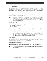
Refer to the specific instructions provided with your VCR and connect the multiplexer’s Record output
to the VIDEO IN connector on your VCR and the multiplexer’s Play input to the VIDEO OUT
connector on your VCR. The drawings above are illustrative of typical multiplexer to VCR
connections.
NOTE:
Both standard (Composite) and S-VHS VCR connections cannot be used at the same
time. Select either standard or S-VHS connections depending on the VCR used.
2.5
MONITOR CONNECTIONS
For Monitor-A (multi-screen), hook-up to the Monitor-A BNC connector, using a 75 ohm coaxial
cable. Connect the other end of the cable to your monitor. For Monitor-B (spot), hook-up to the
Monitor-B, BNC connector, using a 75-ohm coaxial cable. Connect the other end of the cable to your
monitor.
2.6
ALARM INPUTS AND OUTPUTS
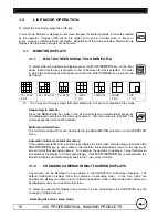
Use the supplied 25 pin D-Sub M connector or interface PCB, wired according to the following
instructions. Do not attempt to wire directly to the 25 pin D-sub connector on the multiplexer back
panel.
This drawing shows the Alarm I/O PCB
supplied with the unit. This wiring interface
greatly simplifies all alarm and VCR
connections to the unit.
PIN NO. (PCB Location)
CONNECTIONS
Pins 1 to 16 (A1-A16)
Alarm inputs 1 to 16
Pin 17 (NO1)
Alarm output 1 – Relay #1 (selectable NO or NC)
Pins 18 to 20 (GND)
Ground connections – Alarms and VEXT inputs
Pin 21 (COM1)
Alarm output 1 – Relay #1 common ground
Pin 22 (NO2)
Alarm output 2 – Relay #2 (selectable NO or NC)
Pin 23 (ACK)
External Alarm clear (pull to ground to clear)
Pin 24 (VEXT)
VEXT, VCR synchronization pulse
Pin 25 (COM2)
Alarm output 2 – Relay #2 common ground
NO1
A1
A2
A14
A15
A16
A3
A4
A5
GND
GND
GND
A6
NO2
COM1
A7
A8
A9
A10
GND
ACK
A11
Vext
A12
A13 COM2
17
1
2
14
15
16
3
4
5
18
19
19
6
Signal
PIN
22
21
7
8
9
10
20
23
11
24
12
13
25
Signal
PIN