


7
Available signals
The following signals can be input to this monitor.
Video signals
Terminal
Available signals
VIDEO IN A terminals
NTSC, PAL, SECAM, PAL60, NTSC4.43, PAL M, PAL N, BW (50 Hz/60 Hz)
VIDEO IN B (RGB/
COMPO.) terminal
Component
signals
480/60i, 576/50i, 480/60p, 576/50p, 720/60p, 720/50p, 1080/60i
(1035/60i)
*1
, 1080/50i, 1080/24psF
RGB signals
15 kHz/50 Hz
*2
, 15 kHz/60 Hz
*2
*1
Select an appropriate setting for High-Definition signal (see “1080/1035“ on page 13).
*2
Interlace signals only
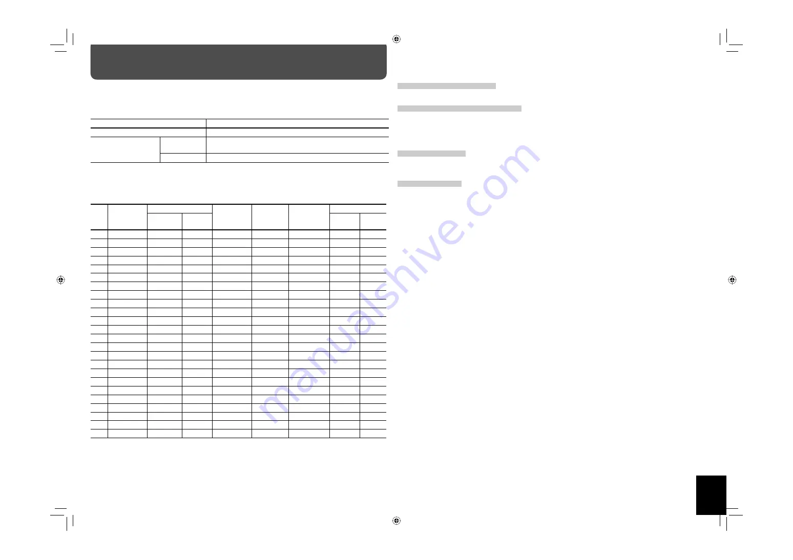
Computer signals (Preset)
VIDEO IN B (RGB/COMPO., DVI-D) terminals
No.
Signal name
Screen resolution
Horizontal
frequency
(kHz)
Vertical
frequency
(Hz)
Scan system
Input terminal
Horizontal
Vertical
RGB/
COMPO.
DVI-D
1
PC98
640
400
24.8
56.4
Non-interlace
√
—
2
VGA400/70
640
400
31.5
70.1
Non-interlace
√
—
3
VGA60
640
480 31.5
59.9
Non-interlace
√
√
4
WVGA60
852
480
31.5
59.9
Non-interlace
√
√
5
VGA72
640
480
37.9
72.8
Non-interlace
√
—
6
SVGA60
800
600
37.9
60.3
Non-interlace
√
√
7
XGA60
1024
768
48.4
60.0
Non-interlace
√
√
8
WXGA60
1366
768
48.4
60.0
Non-interlace
√
√
9
WXGA (1280)
1280
768
47.8
60.0
Non-interlace
√
√
10
WXGA (1360)
1360
768
47.7
60.0
Non-interlace
—
√
11
1280 * 720
1280
720
44.8
60.0
Non-interlace
√
√
12
XGA70
1024
768
56.5
70.1
Non-interlace
√
—
13
XGA75
1024
768
60.0
75.0
Non-interlace
√
—
14
XGA85
1024
768
68.7
85.0
Non-interlace
√
—
15
XGA+75
*3
1152
864
67.5
75.0
Non-interlace
√
—
16
SXGA60
*3
1280
1024
64.0
60.0
Non-interlace
√
√
17
SXGA75
*3
1280
1024
80.0
75.0
Non-interlace
√
—
18
SXGA+60
*3
1400
1050
64.0
60.0
Non-interlace
√
√
19
SXGA+60*
*3
1400
1050
65.2
60.0
Non-interlace
√
√
20
UXGA60
*3
1600
1200
75.0
60.0
Non-interlace
√
—
21
MAC13
640
480
35.0 66.7
Non-interlace
√
—
22
MAC16
832
624
49.7 74.6
Non-interlace
√
—
23
MAC19 1024
768
60.2
74.9
Non-interlace
√
—
24
MAC21
*3
1152
870
68.7 75.1
Non-interlace
√
—
√ : Acceptable
—: Not acceptable
*3
When No. 15 to No. 20 and No. 24 signals are input, thin lines may become obscured because their signal frequencies are higher than the
screen resolution.
Connections
Note for VIDEO IN A (IN, Y/C IN) terminals
When both IN terminal and Y/C IN terminal are used, the input to the Y/C IN terminal has priority.
Note for VIDEO IN B (RGB/COMPO., DVI-D) terminals
Select the correct input for Input B on the main menu (see “INPUT CONFIGURATION” on page 12).
• When RGB signals are input to the RGB/COMPO. terminal: Set “INPUT B” to “ANALOG RGB.”
• When component signals are input to the RGB/COMPO. terminal: Set “INPUT B” to “COMPONENT.”
• When using the DVI-D terminal: Set “INPUT B” to “DVI.”
Note for component signals
• The monitor is compatible only with Y on sync signals. The monitor is not compatible with composite sync (Cs)
and separated sync (HD/VD) signals.
Note for computer signals
• When analog RGB signals are input, part of the picture may not be displayed or an unnecessary picture may
appear in the following cases. Adjust size and position in the “SIZE SETTING” menu (see page 11).
– When a signal other than those listed on the left is input
– When the horizontal/vertical frequency of the signal is different though its resolution is the same as that of the
signals listed on the left
– When the resolution of the signal output from the personal computer is different from that set for the personal
computer’s display.
• Any signal other than those listed on the left may not be displayed normally although it’s frequency is within the
acceptable range.
• Depending on the connected equipment, the monitor may not be compatible with composite sync (Cs) or G on
sync signals.
• When a preset mode signal is input, the signal format is displayed on the screen. For other signals, the horizontal/
vertical frequency or resolution is displayed.
• The DVI-D terminal can accept only No. 3, 4, 6 – 11, 16, 18, and No. 19 signals.
• When the No. 3 and No. 7 signals are input, set the video card of the personal computer to “640 x 480” (for No. 3
signal)/ “1024 x 768” (for No. 7 signal). For analog RGB input, also set “SAMPLING MODE” to “STD” on the set-up
menu (see page 16).
• When the No. 4 and No. 8 signals are input, set the video card of the personal computer to “852 x 480” (for No. 4
signal)/“1366 x 768” (for No. 8 signal). For analog RGB input, also set “SAMPLING MODE” to “WIDE” on the set-up
menu (see page 16), and then change the aspect ratio to “FULL” (see pages 9 and 11).
• When No. 15 to No. 20 and No. 24 signals are input, thin lines may become obscured because their signal
frequencies are higher than the screen resolution.
• When the No. 16 signal is input, set the video card of the personal computer to “1280 x 1024.” For analog RGB
input, also set “SXGA/SXGA+” to “SXGA” on the set-up menu (see page 16).
• When the No. 18 and No. 19 signals are input, set the video card of the personal computer to “1400 x 1050.” For
analog RGB input, also set “SXGA/SXGA+” to “SXGA+” on the set-up menu (see page 16).
GM-H40L2UA_resize-2.indd 7
GM-H40L2UA_resize-2.indd 7
06.7.28 1:44:10 PM
06.7.28 1:44:10 PM