1-9
CA-MXS6MDR
SP-MXS6MD
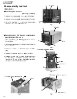
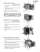
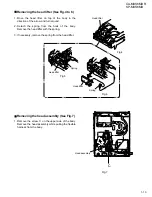
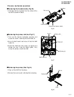
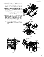
Prior to performing the following procedure, remove
the top cover.
Disconnect the wire from connector CN111 and
CN112 on the tuner board.
Remove the screw J on the side of the body
.
Remove the two screws K on the back of the rear
panel.
1.
2.
3.
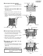
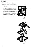
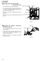
Removing the tuner board
(See Fig.15 and 16)
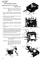
Prior to performing the procedure, remove the top
cover.
Remove the two screws L attaching the rear cover
to the body.
Remove the two screws K, M, N, O, and the screw P
and Q respectively.
Release the joint e on the lower left side of the rear
panel.
1.
2.
3.
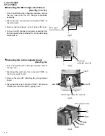
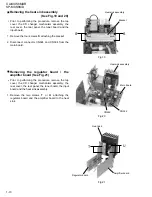
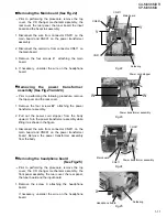
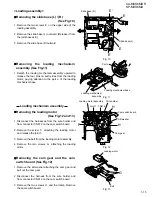
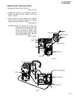
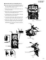
Remove the rear cover / the rear panel
(See Fig.15 and 17)
Prior to performing the procedure, remove the top
cover, the rear cover, the rear panel and the tuner
board.
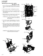
Disconnect the card wire from connector CN661 and
the wire from CN603 on the input board.
Remove the two screws R attaching the bracket and
remove the bracket in the direction of the arrow.
Disconnect the lower connector CN602, CN913 and
CN922 from the main board. Disconnect the wire
from CN691 on the input board.
1.
2.
3.
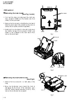
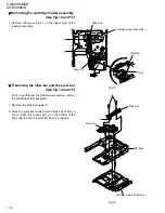
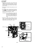
Removing the Input board (See Fig.18)
To facilitate the procedure, remove the
rear panel in advance.
REFERANCE:
CN111
Rear cover
CN661
CN603
Input board
CN691
CN602
CN913
CN922
Joint
e
Tuner board
J
K
L
L
O
Q
K
M
N
R
P
Fig.15
Fig.16
CN112
Rear panel
Rear panel
Fig.17
Fig.18

