1-11
CA-MXS6MDR
SP-MXS6MD
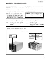
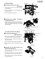
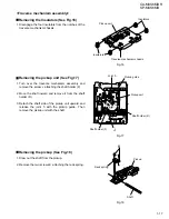
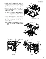
Prior to performing the procedure, remove the top
cover, the CD changer mechanism assembly, the
rear cover, the rear panel, the tuner board, the input
board and the heat sink assembly.
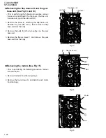
Disconnect the wire from connector CN911 on the
main board and CN991 on the power transformer
assembly.
Disconnect the card wire from connector CN511 on
the main board.
Remove the four screws V attaching the main
board.
If necessary, unsolder the wire on the headphone
board.
1.
2.
3.
4.
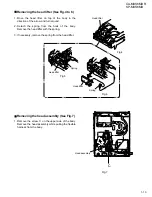
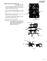
Removing the Main board (See Fig.22)
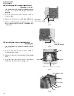
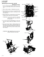
Prior to performing the procedure, remove the top
cover, the CD changer mechanism assembly, the
front panel assembly, the rear cover, the rear panel,
the tuner board and the input board.
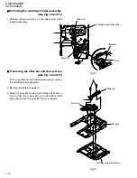
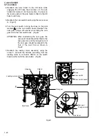
Remove the screw X attaching the headphone
board.
If necessary, unsolder the wire on the headphone
board.
1.
Removing the headphone board
(See Fig.25)
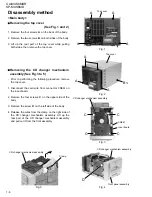
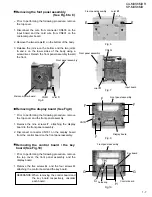
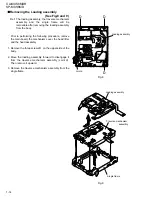
Prior to performing the following procedure, remove
the top cover and the rear cover.
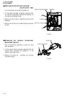
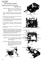
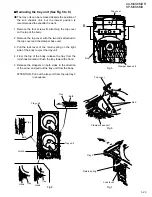
Remove the four screws W attaching the power
transformer assembly.
Pull out the power cord stopper from the body
upward. Turn the power transformer assembly while
lifting it as shown in the figure.
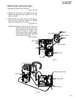
Disconnect the wire from connector CN911 on the
main board and CN991 on the power transformer
board. Remove the power transformer assembly
from the body.
1.
2.
3.
Removing the power transformer
assembly (See Fig.23 and 24)
Main board
CN911
CN991
CN511
Soldering
Power cord stopper
Power transformer assembly
Power transformer assembly
Main board
Headphone board
Soldering
V
W
W
X
V
CN911
CN991
Fig.22
Fig.23
Fig.24
Fig.25

