1-24
CA-MXS6MDR
SP-MXS6MD
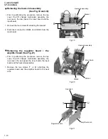
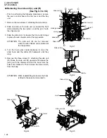
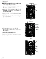
Prior to performing the following procedures, remove
the servo control board, the top cover and the tray
unit.
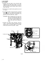
Remove the two screws C attaching the side unit (L).
Slide and remove the side unit (L) toward the front
while releasing the two joints e and the joint f with
the chassis unit.
Slide the slide cam (L) toward the front until it stops
to place the sub chassis unit at the top position.
1.
2.
3.
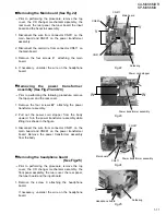
Removing the side unit (L) and (R)
(See Fig.9-1 to 9-5)
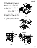
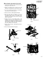
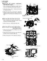
The side unit (R) can be removed
when the sub chassis unit is located at
the top position.
ATTENTION:
Turn the hook gear counterclockwise to move the
slide hook and the slider (R) backward until they
stop.
Remove the three screws D attaching the side unit
(R). Raise the side unit (R) upward and release the
joint g with the chassis unit and the boss from the
select arm marked h. Then remove the side unit (R)
from the body.
4.
5.
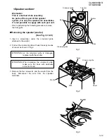
When reassembling, make sure the boss
is fitted to the select arm marked h.
ATTENTION:
Fig.9-1
Fig.9-2
Fig.9-3
Fig.9-5
Fig.9-4
D
D
Side unit (R)
Joints e
Side unit (L)
Joint f
C
Hook gear
slide hook
D
Select arm
Slider (R)
C
Joint h
Side unit (L)
Joints e
Side unit (L)
Joint f
D
Side unit (R)
Joint g
Joint g
Select arm
Boss
D
Side unit (R)
Slide cam(L)
Joint h

