1-7
CA-MXS6MDR
SP-MXS6MD
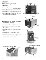
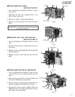
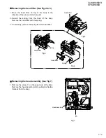
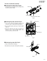
Prior to performing the following procedure, remove
the top cover.
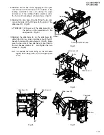
Disconnect the wire from connector CN603 on the
input board and the card wire from CN801 on the
microcomputer board.
Remove the two screws E on the bottom of the body.
Release the joint a on the bottom and the two joints
b and c on the lower sides of the body using a
screwdriver. Detach the front panel assembly toward
the front.
1.
2.
3.
Removing the font panel assembly
(See Fig.6 to 8)
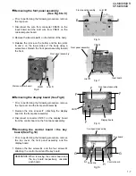
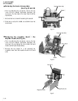
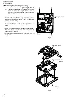
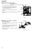
Prior to performing the following procedure, remove
the top cover and the front panel assembly.
Remove the nine screws F attaching the display
board to the front panel assembly.
Disconnect connector CN791 on the display board
from the control board on the front panel assembly.
1.
2.
Removing the display board (See Fig.9)
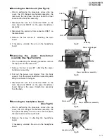
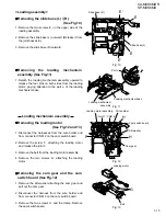
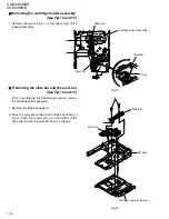
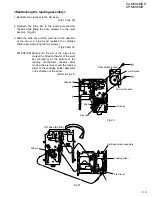
Prior to performing the following procedure, remove
the top cover, the front panel assembly and the
display board.
Remove the five screws G and the four screws H
attaching the control board and the key board.
1.
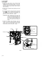
Removing the control board / the key
board (See Fig.10)
When removing the control board and
the key board respectively, unsolder
each board.
REFERANCE:
Fig.8
Front panel assembly
Joint
a
Joint
b
Joint
c
Front panel assembly
CN603
CN801
Microcomputer board
Display board
Key board
Control board
Input board
E
E
F
G
G
G
H
H
F
F
F
Fig.6
Fig.7
Fig.9
Fig.10
Front panel assembly
Front panel assembly
Soldering
Front panel assembly
CN791

