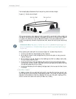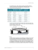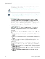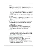
Copyright © 2012, Juniper Networks, Inc.
5
Cables and Pinouts
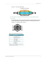
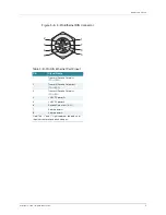
Figure 5–6. 8-Pin Ethernet DIN Connector
Table 3: 8-Pin DIN Ethernet Port Pinout
Pin
Signal Name
1
Transmit/Receive Data plus
(TD/+/RD/+)
2
Transmit/Receive Data minus
(TD/-/RD/-)
3
Transmit/Receive Data plus
(TD+/RD-)
4
+48 VDC power 3+
5
+48 VDC power 3-
6
Receive Data minus (RD-)
7
Return power 4+
8
Return power 4-
Note: The “+” and “-” signs represent the polarity of
the wires that make up each wire pair.
1
7
2
3
4
5
8
6
Содержание WLA620
Страница 12: ...Table of Contents iv ...
Страница 30: ...WLA620 WLA622 and WLA632 Overview 18 Copyright 2012 Juniper Networks Inc ...
Страница 70: ...Installing and Connecting an Access Point 36 Copyright 2012 Juniper Networks Inc ...
Страница 90: ...Cables and Pinouts 6 Copyright 2012 Juniper Networks Inc ...


