background image

Copyright © 2012, Juniper Networks, Inc.

5

Installing and Connecting an Access Point


Using the Wall-Mounting Bracket

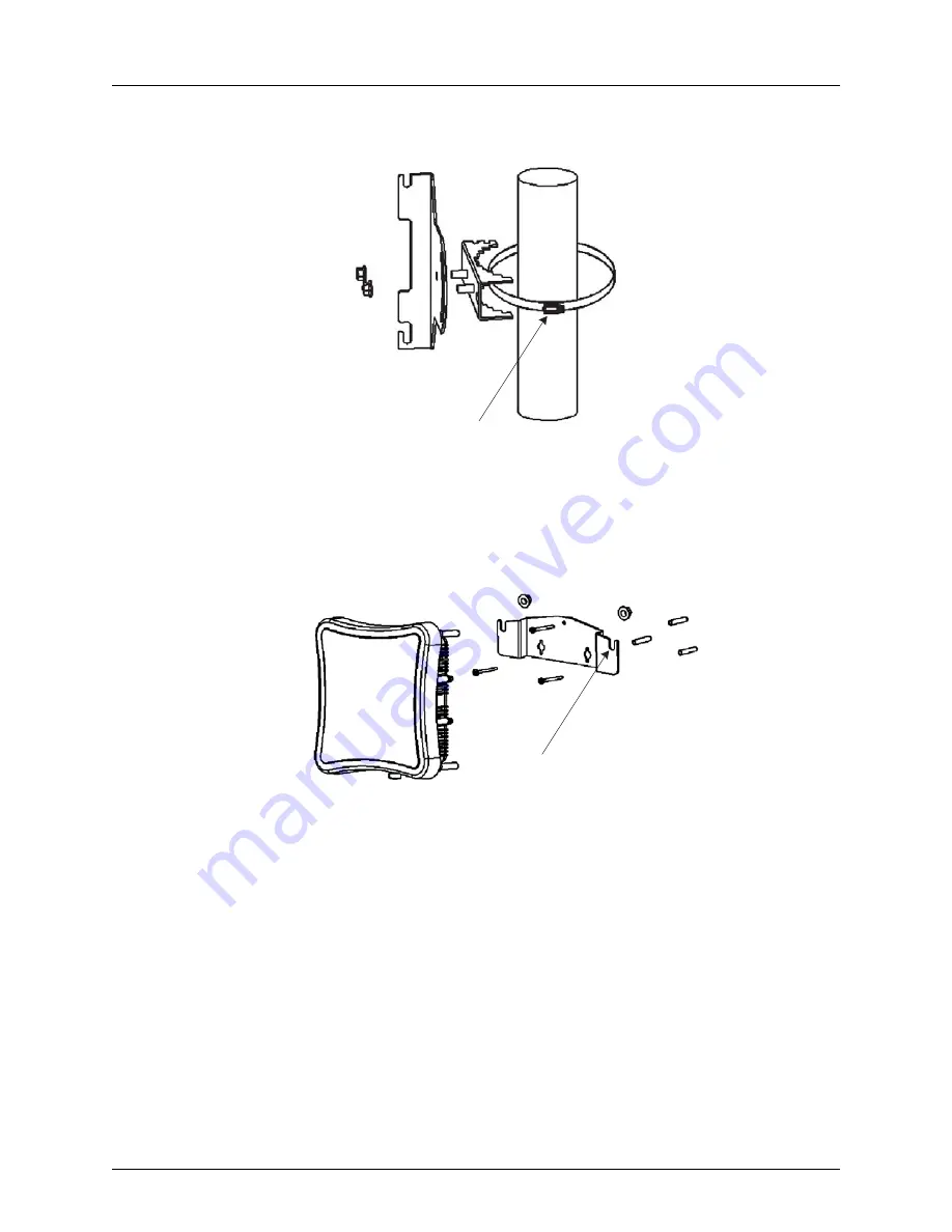
Perform the following steps to mount the unit to a wall using the wall-mounting bracket:

1.

Always attach the bracket to a wall with the open end of the mounting grooves 

facing up (see following figure).

Figure 3–3.  Wall-Mounting Bracket


2.

Position the bracket in the intended location and mark the position of the three 
mounting screw holes.

3.

Drill three holes in the wall that match the screws and wall plugs included in the 
bracket kit, then secure the bracket to the wall.

4.

Use the included nuts to tightly secure the WLA620 to the bracket. 

Connecting External Antennas

When deploying an WLA620, you must mount external antennas and connect them to 
the unit. Typically, access point operation requires a 2.4 GHz antenna, and bridge link 
operation requires a 5 GHz antenna.

Perform these steps:

1.

Mount the external antenna to the same supporting structure as the WLA620, within 

3 m (10 ft) distance, using the bracket supplied in the antenna package.

2.

If you are installing the optional lightning arrestor for an outdoor antenna, perform 
the following steps. Otherwise, skip to step 5.

Steel Band Clamp

Mounting Grooves

Содержание WLA620

Страница 1: ...Juniper Network Inc 1194 N Mathilda Avenue Sunnyvale CA 94089 USA 408 745 2000 www juniper net Part Number 730 9502 0285 Rev C Wireless LAN Access Point Hardware Installation Guide ...

Страница 2: ...the publication of this document They are reliable as of the time of this writing and are presented without warranty of any kind expressed or implied In an effort to continuously improve the product and add features JuniperNetworks reserves the right to change any specifications contained in this document without prior notice of any kind Copyright 2012 Juniper Networks Inc All rights reserved Juni...

Страница 3: ...s Mobility System consists of the following components RingMaster tool suite A full featured graphical user interface GUI application used to plan configure deploy and manage a WLAN and its users One or more Wireless Lan Controller WLC Distributed intelligent machines for managing user connectivity connecting and powering Mobility Point MP access points and connecting the WLAN to the wired network...

Страница 4: ...s supported on WLC appliances and APs Juniper Networks Documentation Conventions Safety and Advisory Notices The following types of safety and advisory notices appear in this guide Hypertext Links Hypertext links appear in Blue As an example this is a link to Contacting the Technical Assistance Center Text and Syntax Conventions Juniper Networks guides use the following text and syntax conventions...

Страница 5: ... number cell phone or pager number and e mail address Name model and serial number of the product s requiring service Software version s and release number s Output of the show tech support command Wireless client information License levels for RingMaster and Mobility Exchange MX products Description of any problems and status of any troubleshooting effort Menu Name Command Indicates a menu item F...

Страница 6: ...mited Hardware Warranty extends only to the Customer who was the original purchaser of the hardware and may not be transferred to any subsequent repurchasing entity During the Limited Hardware Warranty period upon proper notice to Juniper Networks by Customer Juniper Networks will at its sole option either Repair and return of the defective hardware Replace the defective hardware with a new or ref...

Страница 7: ...arranty Disclaimer EXCEPT AS SPECIFIED IN THIS LIMITED WARRANTY ALL EXPRESS OR IMPLIED CONDITIONS REPRESENTATIONS AND WARRANTIES INCLUDING WITHOUT LIMITATION ANY IMPLIED WARRANTY OR CONDITION OF MERCHANTABILITY FITNESS FOR A PARTICULAR APPLICATION OR PURPOSE NONINFRINGEMENT SATISFACTORY QUALITY OR ARISING FROM A COURSE OF DEALING LAW USAGE OR TRADE PRACTICE ARE HEREBY EXCLUDED TO THE EXTENT ALLOWE...

Страница 8: ...cement materials to Customer 9 Miscellaneous The Limited Warranty shall be governed by and construed in accordance with the laws of the State of California without reference to that State s conflict of laws rules and as if the contract was wholly formed within the State of California Customer agrees that jurisdiction and venue shall be in Santa Clara County California Under no circumstances shall ...

Страница 9: ...d Benefits 1 6 External Hardware Features for the WLA622 1 7 LED Indicators 1 8 External Antenna Options 1 9 Ethernet Port 1 9 Power Injector Module 1 10 Grounding Point 1 10 Water Tight Test Point 1 11 Wall and Pole Mounting Bracket Kits 1 11 Lightning Protector for Outdoor Antenna 1 11 System Configuration 1 11 Features and Benefits 1 11 External Hardware Features for the WLA632 1 13 External An...

Страница 10: ...8 Connecting the Power Injector 3 18 Checking the LED Indicators 3 19 Connecting a WLA to a WLC 3 20 Aligning Antennas for Bridge or Mesh Links 3 22 Installing an WLA632 3 24 Mounting the Unit 3 24 Connecting External Antennas 3 28 Multiple External Antenna Support 3 29 High Power Mode 3 29 Ethernet 3 29 Connecting Cables to the Unit 3 30 Connecting the Power Injector 3 30 Connecting an WLA to an ...

Страница 11: ...1 10 100BASE TX Pin Assignments 5 1 Straight Through Wiring 5 2 Crossover Wiring 5 2 8 Pin DIN Connector Pinout for the WLA620 and WLA622 5 3 8 Pin DIN to RJ 45 Cable Wiring 5 3 WLA632 External Connectors 5 4 Ethernet 5 4 Chapter 6 Wireless Bridge Link Planning Radio Path Planning 6 1 Antenna Height 6 2 Radio Interference 6 3 Weather Conditions 6 3 Ethernet Cabling 6 4 Grounding 6 5 WLA622 Antenna...

Страница 12: ...Table of Contents iv ...

Страница 13: ...LANs or to provide Internet access to an isolated site where a wired link may be difficult or expensive to deploy The wireless bridge connection provides data rates of up to 108 Mbps Radio Characteristics The IEEE 802 11a and 802 11g standards use a radio modulation technique known as Orthogonal Frequency Division Multiplexing OFDM and a shared collision domain CSMA CA The 802 11a standard operate...

Страница 14: ...ilable from Juniper Networks WLA XPS9001GO Power Supply Unit The WLA XPS9001GO PSU has separate SKUs for North American and International users WLA XPS9001GO NA An outdoor 802 3at compliant 100 240 VAC 50 60Hz input Gigabit PoE midspan PSU with a North American connector that ships with the mounting bracket This PSU and NA connector is intended for use in countries following North America Safety S...

Страница 15: ...e tabular lug for AWG 8 ground cable Antenna connector terminator Any unused antenna connector on an active radio must be terminated Contact Juniper Networks if there are any incorrect missing or damaged parts If possible retain the carton including the original packing materials Use them again to repack the product in case there is a need to return it External Hardware Features for the WLA620 Fig...

Страница 16: ... WLA620 receives power through the network cable connection using power over Ethernet technology A power injector module is included in the WLA620 package and provides two RJ45 Ethernet ports one for connecting to the WLA620 Output and the other for connecting to a WLC switch or a local LAN switch Input Table 1 External Antenna Options Antenna Type Gain dBi HPBW Horizontal HPBW Vertical Polarizati...

Страница 17: ...al Strength Indicator RSSI BNC Connector The RSSI connector provides an output voltage that is proportional to the received radio signal strength A DC voltmeter can be connected the this port to assist in aligning the antennas at both ends of a wireless bridge link Grounding Point Even though the WLA620 includes a built in lightning protection it is important that the unit is properly connected to...

Страница 18: ...l antenna options Maximum data rate up to 108 Mbps on the 802 11a 5 GHz radio Outdoor weatherproof design IEEE 802 11a and 802 11b g compliant Local network connection via 10 100 Mbps Ethernet port Powered through its Ethernet cable connection to the power injector module Includes wall and pole mount brackets Security through 64 128 152 bit Wired Equivalent Protection WEP or 128 bit Advanced Encry...

Страница 19: ...0 WLA622 and WLA632 Overview External Hardware Features for the WLA622 Figure 1 5 MP Access Point Model WLA622 Bottom View Figure 1 6 Access Point Model WLA622 Top View Antenna ports are numbered from the left 1 to 4 Port 1 Port 2 Port 3 Port 4 ...

Страница 20: ...Activity Ethernet Link Activity 802 11b g Wireless Link Activity Table 2 External Antenna Options LED Status Description Power Green Indicates that the system is working normally Amber Indicates a system reset Off The bridge is not receiving power or there is a fault with the power supply Link Green Indicates a valid 10 100 Mbps Ethernet cable link with no activity Flashing Green Indicates that th...

Страница 21: ...e connector 1 for 2 4 GHz and connector 3 for 5Ghz 11b g three LEDs Slow Flashing Amber The 802 11b g radio is enabled with a low level of network activity Fast Flashing Amber Indicates a medium level of network activity Off No signal detected or the 802 11b g radio is disabled Table 4 Wireless Status LEDs in RSSI Mode LED Status Description 11a three LEDs Off No signal detected or the 802 11a rad...

Страница 22: ...ckets from the wired LAN to the remote end of the wireless bridge link Power Injector Module The WLA622 receives power through the network cable connection using Power over Ethernet PoE technology An outdoor power injector module is available seperately and provides two RJ45 Ethernet ports one for connecting to the WLA622 PoE Output and the other for connecting to an WLC or a local LAN switch Data...

Страница 23: ...o the unit Water Tight Test Point Wall and Pole Mounting Bracket Kits The WLA622 includes bracket kits that can be used to mount the unit to a wall pole radio mast or part of a tower structure Lightning Protector for Outdoor Antenna If you are using the WLA622 with an outdoor antenna Juniper Networks strongly recommends installing an external lightning protector for the antenna An external lightni...

Страница 24: ... IEEE 802 11a and 802 11b g compliant Local network connection via 10 100 Mbps Ethernet port Powered through its Ethernet cable connection to the power injector module Includes wall and pole mount brackets Security through 64 128 152 bit Wired Equivalent Protection WEP or 128 bit Advanced Encryption Standard AES encryption Scans all available channels and selects the best channel and data rate bas...

Страница 25: ...Copyright 2012 Juniper Networks Inc 13 WLA620 WLA622 and WLA632 Overview External Hardware Features for the WLA632 2 4GHz Antenna Ports LEDs 5GHz Antenna Ports Power Ethernet Port ...

Страница 26: ...d If the RJ45 cable ends are correctly inserted the unit will function normally Table 5 WLA632 LED Functions LED Status Description Health Solid green All the following are true Management link with an WLC is operational WLA has booted WLA has received a valid configuration from an WLC At least one radio is enabled or is in sentry mode Solid amber WLA is waiting to receive boot instructions and a ...

Страница 27: ...s outdoors Multiple External Antenna Support The WLA632 supports the use of multiple antenna ports per radio Since there are always multiple antennas connected antenna diversity is always on The command to set the number of external antennas does not apply to the WLA632 The number of antenna ports in use is determined by the antenna type set ap num radio num external antennas num If the ANT 5007 O...

Страница 28: ...ling an external lightning protector for the antenna An external lightning protector may be obtained from Juniper Networks System Configuration At each location where an WLA632 unit is installed it must be connected to the local network but the power injector is not required The following figure illustrates the system component connections Caution If you convert the 8 pin female circular DIN data ...

Страница 29: ...and 128 bit WEP Seamless roaming within the IEEE 802 11 a b g n WLAN infrastructure Adjustable output power support Interoperability with Juniper Networks Wireless Security Switch Auto sensing 10 100 1000 Ethernet port with auto MDI MDI X but has no PoE support on the 10 100 100 data port Comply with IEEE 802 3 802 3u and 802 3ab Powered by 30W 48Vdc outdoor AC DC power supply LAN Switch Indoor Ou...

Страница 30: ...WLA620 WLA622 and WLA632 Overview 18 Copyright 2012 Juniper Networks Inc ...

Страница 31: ...2 only The WLA620 WLA622 and WLA632 have weatherproof casing and can be installed outdoors for example on a pole to provide network access to clients located outside Figure 2 1 Infrastructure Topology with Outdoor WLA The WLA620 WLA622 and WLA632 can be connected directly to an WLC or indirectly over the network Power must be available at the location where the WLA620 WLA622 or WLA632 is installed...

Страница 32: ...Mesh Topology In the illustration a client is associated with a Mesh WLA which is a WLA without a wired interface to the network The Mesh WLA is configured to communicate with a Mesh Portal WLA an WLA with wired connectivity to an WLC Communication between the Mesh WLA and the Mesh Portal WLA takes place over a secure radio link a Mesh Link When associated with the Mesh WLA the client has the same...

Страница 33: ...dge is established between a Mesh Portal WLA and a Mesh WLA to which it is associated The data packets that are bridged are those present on the Ethernet interfaces of the two WLAs A Mesh WLA serving as a bridge endpoint picks up packets from a wired port and transfers them to the other bridge endpoint A simple source destination learning mechanism is used to avoid forwarding packets across the br...

Страница 34: ...2012 Juniper Networks Inc WLA620 Mesh Portal WLA with Omnidirectional Antenna WLA620 Mesh WLA WLA620 Mesh WLA WLA620 Mesh WLA WLA620 Mesh WLA WLA620 Mesh WLA WLA620 Mesh Portal WLA with Sector Antenna WLA620 Mesh WLA WLA620 Mesh WLA WLA620 Mesh WLA ...

Страница 35: ...stall and configure the WLC before installing a WLA If the WLC is already installed and configured for the WLAs you can immediately verify the cable connection s when you plug the cable s into the WLA Weather Conditions When planning an WLA620 WLA622 or WLA632 installation you must take into account any extreme weather conditions that are known to affect your location Consider the following factor...

Страница 36: ...ect on the radio signal However it is recommended to apply weatherproof sealing tape around the Ethernet port and antenna connectors for extra protection If moisture enters a connector it may cause a degradation in performance The WLA632 weatherproof enclosure is designed to protect against dust rain and water jets Snow and Ice Falling snow like rain has no significant effect on the radio signal H...

Страница 37: ...ironmental limits found in OET 65 and ANSI C95 1 1991 Proper installation of the MP access point according to the instructions in this manual will result in user exposure that is below the FCC recommended limits Additional Radio Safety Advisories For additional radio safety warnings the Regulatory Guide document Installing a WLA620 The WLA620 includes a bracket kit for mounting the unit to a 3 81 ...

Страница 38: ...he Pole 3 Use the included nuts to tightly secure the WLA620 to the bracket Mounting on Larger Diameter Poles In addition there is a method for attaching the pole mounting bracket to a pole that is 5 08 to 12 7 cm 2 to 5 inches in diameter using an adjustable steel band strap not included in the kit A steel band strap up to 0 5 inch 1 27 cm wide can be threaded through the main part of the bracket...

Страница 39: ...wall plugs included in the bracket kit then secure the bracket to the wall 4 Use the included nuts to tightly secure the WLA620 to the bracket Connecting External Antennas When deploying an WLA620 you must mount external antennas and connect them to the unit Typically access point operation requires a 2 4 GHz antenna and bridge link operation requires a 5 GHz antenna Perform these steps 1 Mount th...

Страница 40: ...F coaxial cable to the WLA620 N type connector and connect the other end to the lightning arrestor b Connect one end of the 3m RF coaxial cable to the lightning arrestor and connect the other end to the outdoor antenna Continue with step 6 5 Connect the antenna to the WLA620 N type connector using the RF coaxial cable provided in the antenna package 6 Apply weatherproofing tape to the antenna conn...

Страница 41: ...oofing tape not included around the Ethernet connector RF Coaxial Cable 2 4 GHz External Omnidirectional Antenna 2 4 GHz N type Connector 5 GHz N type Connector 5 GHz External High gain Panel Antenna Optional Lightning Protector MP 620 Informational Note The Ethernet cable included with the package is 30 m 100 ft long To wire a longer cable maximum 100 m 325 ft use the connector pinout information...

Страница 42: ... the CLI or RingMaster to configure an WLA connection If you are installing the WLA620 as a Mesh WLA in a WLAN Mesh or wireless bridge configuration you must configure the WLA connection before deploying the WLA620 in its final location Figure 3 7 below shows how to insert a Cat 5 cable into 10 100 Ethernet port on an WLC Refer to this figure as you perform the procedure Figure 3 7 10 100 Cat 5 Ca...

Страница 43: ...ligned with the Mesh Portal antenna The alignment process is the same as for point to point links but only the Mesh WLA end of the link requires the alignment The WLA620 BNC connector provides an output voltage between 0 and 3 28 VDC that is proportional to the received radio signal strength The higher the voltage reading the stronger the signal The radio signal from the remote antenna can be seen...

Страница 44: ...ignal strength of the packet This can aid in positioning the WLA620 where it has a strong signal to the WLA sending out the packets To configure an WLA radio to send out link calibration packets use the following command on the WLC set ap num radio num link calibration mode enable disable Only one radio on a WLA can be configured to send link calibration packets Link calibration packets are intend...

Страница 45: ...the horizontal adjustment in that position 5 Loosen the vertical adjustment on the mounting bracket and tilt the antenna slowly up and down while checking the RSSI voltage 6 Find the point where the signal is strongest and secure the vertical adjustment in that position 7 Remove the voltmeter cable and replace the connector cover Voltmeter RSSI BNC Connection Informational Note Sometimes there may...

Страница 46: ...C power source 5 For wireless bridge or Mesh Services installations align antennas at the bridge or mesh link endpoints Mounting the Unit You can mount the WLA622 using either the pole mounting bracket or the wall mounting bracket Use one of the following procedures Using the Pole Mounting Bracket Perform the following steps to mount the unit to a 3 81 to 5 08 cm 1 5 to 2 inch diameter steel pole ...

Страница 47: ...13 Installing and Connecting an Access Point Figure 3 10 Attaching the Bracket to the Pole 2 Fit the edges of the V shaped part into the slots in the rectangular plate and use the included nuts to tightly secure the WLA622 to the bracket ...

Страница 48: ... the bridge with bracket to the plate already fixed to the pole 5 Use the included nuts to secure the wireless bridge to the pole bracket Note that the wireless bridge tilt angle may need to be adjusted during the antenna alignment process Be sure to take account of the antenna polarization direction All antennas in a link must be mounted with the same polarization ...

Страница 49: ...a larger diameter pole without using the U shaped part of the bracket This method is illustrated in the following figure Figure 3 11 Attaching the Bracket Using a Steel Band strap Using the Wall Mounting Bracket Perform the following steps to mount the unit to a wall using the wall mounting bracket 1 Always attach the bracket to a wall with the flat side flush against the wall see following figure...

Страница 50: ... each band If you install one antenna it must be installed in the primary port If you install two antennas they must be the same antenna model There are no additional configuration requirements for adding the second antenna If antenna diversity between the two antennas is a desired option it must be configured The default for the 802 11bg radio is ANT 1360 OUT set ap apnum radio num antennatype AN...

Страница 51: ...RF coaxial cable to the WLA622 N type connector and connect the other end to the lightning arrestor d Connect one end of the 3m RF coaxial cable to the lightning arrestor and connect the other end to the outdoor antenna Continue with step 6 3 Connect the antenna to the WLA622 N type connector using the RF coaxial cable provided in the antenna package 4 Apply weatherproofing tape to the antenna con...

Страница 52: ...erproofing tape not included around the Ethernet connector 4 Be sure to install a lightning arrestor on the Ethernet cable between the bridge and power injector The lightning arrestor should be placed outdoors immediately before the Ethernet cable enters the building RF Coaxial Cable 2 4 GHz External Omnidirectional Antenna 2 4 GHz N type Connector 5 GHz N type Connector 5 GHz External High gain P...

Страница 53: ...nnect the wireless bridge to a PSU 1 Connect the Ethernet cable from the wireless bridge to the PoE port labeled DATA PWR OUT on the PSU Informational Note The Ethernet port on the wireless bridge does not support Power over Ethernet PoE based on the IEEE 802 3af standard Do not try to power the unit by connecting it directly to a WLC that provides IEEE 802 3af PoE For power always connect the uni...

Страница 54: ...g appropriate for your country Table 2 11a and 11b g LED Behavior on the WLA622 LED Appearance Meaning Power Green The bridge is powered up and operating normally Off The bridge is not receiving power or there is a fault with the power supply Amber The system is under cold reset status Link Green The bridge has a 10 100 Mbps Fast Ethernet connection but there is no activity Flashing Indicates that...

Страница 55: ...rm the procedure Figure 3 16 10 100 Cat 5 Cable Installation 1 Insert a Cat 5 cable with a standard RJ45 connector as shown in Figure 3 7 For connection to an WLA use a straight through cable 11g Three LEDs Amber and Flashing The 802 11g 2 4 GHz radio is enabled RSSI Mode One fully lit LED indicates a low RSSI output level two LEDs a medium level and three LEDs the maximum level A flashing LED ind...

Страница 56: ... point to point links but only the Mesh WLA end of the link requires the alignment The LEDs are viewed right to left as you look at the back of the WLA The range from 1 to 12 will cover the signal range to accurately align the antenna The signal strength LEDs indicate the received radio signal strength for a particular bridge link The more LEDs that turn on the stronger the signal RSSI level 1 sho...

Страница 57: ... being aligned with set ap num radio num link calibration mode enable disable Link calibration should be disabled under normal operation of the WLA If the WLA622 is installed with two directional antennas connect the first antenna to the primary antenna port with antenna diversity off and align it Then disconnect the first antenna and connect the second antenna to the primary antenna port If the s...

Страница 58: ...s may require a different horizontal adjustment 2 Find the point where the signal is strongest all LEDs on and secure the horizontal adjustment in that position 3 Loosen the vertical adjustment on the mounting bracket and tilt the antenna slowly up and down while checking the LEDs Find the point where the signal is strongest and secure the vertical adjustment in that position Informational Note So...

Страница 59: ...t cable and a grounding wire to the unit 4 Connect the other end of the circular DIN power cable to the WLA XPS9001GO 5 Connect the circular DIN Ethernet cable and prepare the RJ45 cable with the waterproof cover that is provided Mounting the Unit You can mount the WLA632 using either the wall mounting bracket or the wall mounting bracket combined with the pole mounting bracket brackets are provid...

Страница 60: ...niper Networks Inc 1 Insert the four large screws included in kit through the four circular holes in the bracket as shown below 2 Position the flat bracket behind the pole as shown below and align the screws on the front bracket with the holes in the flat bracket ...

Страница 61: ... Access Point 3 Insert the four screws into the holes on the flat bracket and secure the brackets to the pole using the provided split washers and nuts 4 Position the WLA632 unit so that the mounting holes overlap with the same sized holes on the pole mounting bracket ...

Страница 62: ... is also a method for attaching the pole mounting bracket to a larger diameter pole using two adjustable steel band straps not included in the kit The two steel band straps can be threaded through the rectangular holes in the bracket to secure it to a larger diameter pole This method is shown in the following figure Informational Note This pole mounting procedure can also be used to attached the W...

Страница 63: ...s to mount the unit to a wall using the wall mounting bracket Figure 3 19 Wall Mounting Bracket 1 Position the bracket on the intended wall location and drill four large screws not included in kit in through the circular holes on the bracket until it is firmly secured to the wall Informational Note Always attach the bracket to a wall with the flat side flush against the wall see following figure ...

Страница 64: ...ized holes on the wall mounted bracket 3 Use the 2 small bolts and washers included in kit to tightly secure the WLA632 to the wall mounted bracket Connecting External Antennas The supported antennas models are 802 11bgn Radio ANT 7360A OUT stick N type jack If this antenna is used the unused center antenna port must be terminated ANT 77555 OUT 3 RP SMA jack ...

Страница 65: ...ntennas does not apply to the WLA632 The number of antenna ports in use is determined by the antenna type set ap num radio num external antennas num If the external antenna command is used for the WLA632 it will be ignored at the CLI If the ANT 5007 OUT antenna is in use on the 11a n radio then the radio configuration will revert to 2 x 3 mode rather than 3 x 3 mode and the middle port for the rad...

Страница 66: ...e to the lightning arrestor and connect the other end to the outdoor antenna Continue with step 6 3 Connect the antenna to the WLA632 N type connector using the RF coaxial cable provided in the antenna package 4 Apply weatherproofing tape to the antenna connectors to help prevent water entering the connectors Connecting Cables to the Unit 1 Ground the unit with an appropriate grounding wire not in...

Страница 67: ...power cable into a grounded 3 pin socket AC power source Informational Note Be sure that grounding is available and that it meets local and national electrical codes For additional lightning protection use lightning rods lightning arrestors or surge suppressors Informational Note The Ethernet port on the wireless bridge does not support Power over Ethernet PoE based on the IEEE 802 3af standard Do...

Страница 68: ... following are true Management link with an WLC is operational WLA has booted WLA has received a valid configuration from an WLC At least one radio is enabled or is in sentry mode Solid amber WLA is waiting to receive boot instructions and a configuration file from an WLC Alternating green and amber WLA is booting and receiving a configuration file from an WLC After the WLA boots and receives a co...

Страница 69: ...d from the WLC switch After the access point boots and receives its configuration this LED appearance persists until a radio is enabled or is placed in sentry mode Solid amber PoE is on Blinking amber WLA is unresponsive or there is a PoE problem Unlit PoE is off Alternating green and amber WLA is booting with an image received from the WLC switch After the access point boots and receives its conf...

Страница 70: ...Installing and Connecting an Access Point 36 Copyright 2012 Juniper Networks Inc ...

Страница 71: ...sing the RingMaster management application or the WLC s command line interface CLI Informational Note Regulatory Obligation The radio frequency band operating channels and transmit power depend on the country of operation specified by the system administrator using RingMaster or the WLC s CLI Table 1 WLA620 and WLA622 Mechanical and Compliance Specifications Specification Description Maximum Chann...

Страница 72: ...10 58 lbs Weight WLA622 1 54 kg 3 4 lbs Temperature WLA620 Operating 33 to 55 C 27 4 to 131 F Storage 40 to 80 C 40 to 176 F Temperature WLA622 Operating 30 to 55 C 22 to 131 F Storage 40 to 80 C 40 to 176 F Humidity 5 to 95 non condensing EMC Compliance Class B FCC Class B US RTTED 1999 5 EC DGT Taiwan Radio Signal Certification FCC Part 15 15 407 b 5 GHz FCC Part 15 247 2 4 GHz IC RSS 210 EN 300...

Страница 73: ...140 For indoor application only channels 36 48 52 64 Japan 8 channels Modulation Types 802 11a OFDM BPSK QPSK 16 QAM 64 QAM 802 11b g DSSS DBPSK DQPSK CCK OFDM BPSK QPSK 16 QAM 64 QAM 802 11n DSSS DBPSK DQPSK CCK OFDM BPSK QPSK 16 QAM 64 QAM Operating Frequency Radio 1 supports 2 4 GHz to 2 4835 GHz Channels 1 to 14 Radio 2 supports 5 15 GHz to 5 35 GHz Channels 52 to 64 36 to 48 for Hong Kong onl...

Страница 74: ...let on a circuit different from that to which the receiver is connected Consult the dealer or an experienced radio TV technician for help This device complies with Part 15 of the FCC Rules Operation is subject to the following two conditions 1 This device may not cause harmful interference and 2 this device must accept any interference received including interference that may cause undesired opera...

Страница 75: ...h this device The required antenna impedance is 50 ohms The device could automatically discontinue transmission in case of absence of information to transmit or operational failure Note that this is not intended to prohibit transmission of control or signaling information or the use of repetitive codes where required by the technology The device for the band 5150 5250 MHz is only for indoor usage ...

Страница 76: ...or WLA620 and WLA622 8 dBi Omnidirectional 2 4 GHz Caution IC Radiation Exposure Statement This equipment complies with IC RSS 102 radiation exposure limits set forth for an uncontrolled environment This equipment should be installed and operated with minimum distance 20cm between the radiator your body Table 3 MAC Address Allocations on WLA620 WLA622 and WLA632 WLA base MAC Address The WLA has a ...

Страница 77: ... type male Radome Material Fiber glass Color Gray white Environmental Survival Wind Speed 216 km hr 134 mph Temperature 40 C to 80 C 40 F to 176 F Humidity 95 25 C 77 F Mechanical Dimensions 58 x 2 1 cm diameter 22 8 x 0 82 in Weight 200 g 0 44 lbs Table 5 8 dBi Omnidirectional 5 GHz Antenna Specifications Specification Description Model Number ANT 5360 OUT Frequency Range 5 725 5 875 GHz Gain 8 d...

Страница 78: ...ification Description Model Number ANT 5120 OUT Frequency Range 5 150 5 875 GHz Gain 13 5 dBi VSWR 2 0 1 max Polarization Linear vertical HPBW Horizontal 120 Vertical 6 Downtilt 0 Power Handling 5 W cw Impedance 50 Ohms Connector N type female Radome Material ABS Color Gray white Environmental Survival Wind Speed 216 km hr 134 mph Temperature 40 C to 80 C 40 F to 176 F Humidity 95 25 C 77 F Mechan...

Страница 79: ...cy Range 2 4 2 5 GHz Gain 10 dBi VSWR 2 0 1 max Polarization Linear vertical HPBW Horizontal 120 Vertical 15 Downtilt 0 Power Handling 10 W cw Impedance 50 Ohms Connector N type female Radome Material ABS Color Gray white Environmental Survival Wind Speed 216 km hr 134 mph Temperature 40 C to 80 C 40 F to 176 F Humidity 95 25 C 77 F Mechanical Dimensions 75 x 8 8 x 7 cm 29 5 x 3 46 x 2 76 in Weigh...

Страница 80: ...Vertical 18 Downtilt 0 Power Handling 5 W cw Impedance 50 Ohms Connector N type female Radome Material ABS Color Gray white Environmental Survival Wind Speed 216 km hr 134 mph Temperature 40 C to 80 C 40 F to 176 F Humidity 95 25 C 77 F Mechanical Dimensions 21 5 x 20 x 5 cm 8 46 x 7 87 x 1 97 in Weight 825 g 1 82 lbs Table 9 Signal Loss Levels from Lightning Protector and Coaxial Cable Frequency ...

Страница 81: ...nt antennas an antenna with multiple antenna elements have multiple antenna cables one for each antenna element Some single element omni stick antennas on the other hand do not require an antenna cable in order to attach to an antenna connector Table 10 WLA632 Antenna Specifications Conn Name Connector Type Use Label Antenna 1 N Type Jack 1st Antenna Element for Radio 1 2 4GHZ Ant 1 Antenna 2 N Ty...

Страница 82: ...ntenna elements in use will be identical to the number of antenna connectors in use It is important to understand that the number of antennas for a given radio and the number of antenna elements and antenna connectors in use for that radio are not necessarily the same The figure shown above demonstrates that there are three antennas in use for radio 1 and there are also three antenna elements in u...

Страница 83: ...levels across a 35dB dynamic range from a high of 60 dBm to a low of 95 dBm The RSSI is indicated by on off flashing LED patterns as shown in the table below The granularity varies between 2dBm 3dBm and 6dBm ANT 77555 OUT 2 4GHz 1 Conn 1 2 3 Dual band Tri element Directional Panel 3x3 5GHz 1 Conn 4 5 6 3x3 ANT 5007 OUT 5GHz 1 Conn 4 6 Single band Dual element Directional Panel 2x3 Table 11 Juniper...

Страница 84: ...Series Technical Specifications 14 Copyright 2012 Juniper Networks Inc On On Off Operational signal On On Flashing Slow On On Flashing Fast On On On Strong signal Table 13 2 4G Ch 13 LED 1 LED 2 LED 3 RSSI ...

Страница 85: ...old the connectors in the same orientation when attaching the wires to the pins Figure 5 1 Pin Numbering on RJ45 Connector 10 100BASE TX Pin Assignments Use unshielded twisted pair UTP or shielded twisted pair STP cable for RJ45 connections 100 ohm Category 3 or better cable for 10 Mbps connections or 100 ohm Category 5 or better cable for 100 Mbps connections Also be sure that the length of any t...

Страница 86: ...ring Because the 10 100 Mbps port on the power injector uses an MDI pin configuration you must use crossover cable for network connections to PCs servers or other end nodes that only have MDI ports However if the device to which you are connecting supports automatic MDI MDI X operation you can use either straight through or crossover cable Table 1 10 100BASE TX MDI and MDI X Port Pinouts Pin MDI X...

Страница 87: ...t DIN Connector Table 2 8 Pin DIN Ethernet Port Pinout Pin Signal Name 1 Transmit Data plus TD 2 Transmit Data minus TD 3 Receive Data plus RD 4 48 VDC power 5 48 VDC power 6 Receive Data minus RD 7 Return power 8 Return power Note The and signs represent the polarity of the wires that make up each wire pair White Orange Stripe Orange White Green Stripe 1 2 3 4 5 6 7 8 1 2 3 4 5 6 7 8 EIA TIA 568B...

Страница 88: ... single IEEE 802 3 compliant auto sensing 10 100 1000BaseT Ethernet interface on the Ethernet input connector It should be configured as auto MDI MDIX The Ethernet interface supports a cable length of at least 100m over CAT5 CAT5e or CAT6 cable A watertight RJ45RJ45 is an acceptable alternative to the circular DIN connector for the Ethernet interface The Ethernet cable from the power injector conn...

Страница 89: ... Port Pinout Pin Signal Name 1 Transmit Receive Data plus TD RD 2 Transmit Receive Data minus TD RD 3 Transmit Receive Data plus TD RD 4 48 VDC power 3 5 48 VDC power 3 6 Receive Data minus RD 7 Return power 4 8 Return power 4 Note The and signs represent the polarity of the wires that make up each wire pair 1 7 2 3 4 5 8 6 ...

Страница 90: ...Cables and Pinouts 6 Copyright 2012 Juniper Networks Inc ...

Страница 91: ...ne of sight involves the area along a radio link path through which the bulk of the radio signal power travels This area is known as the first Fresnel Zone of the radio link For a radio link not to be affected by obstacles along its path no object including the ground must intrude within 60 of the first Fresnel Zone Informational Note The planning and installation of a wireless bridge link require...

Страница 92: ...sure there is enough clearance from buildings and that no building construction may eventually block the path Check the topology of the land between the antennas using topographical maps aerial photos or even satellite image data software packages are available that may include this information for your area Avoid a path that may incur temporary blockage due to the movement of cars trains or aircr...

Страница 93: ...ast 22 3 m 73 ft high Building A is six stories high or 20 m 66 ft so a 2 3 m 7 5 ft mast or pole must be constructed on its roof to achieve the required antenna height Building B is only three stories high or 9 m 30 ft but is located at an elevation that is 12 m 39 ft higher Table 1 Required Clearance Above Obstructions Total Link Distance Max Clearance for 60 of First Fresnel Zone at 5 8 GHz App...

Страница 94: ...ollowing factors Temperature Operating a WLA in temperatures outside of the supported range may cause the unit to fail The WLA620 is tested for normal operation in temperatures from 33 C to 55 C 27 4 to 131 F The WLA622 is tested for normal operation in temperatures from 30 to 55 C 22 to 131 F The WLA632 is tested for an ambient operating temperature range of 40 C to 50 C 40 to 122 F Wind Velocity...

Страница 95: ...injector module indoors Consider these points The Ethernet cable length should never be longer than 100 m 328 ft over CAT5 CAT5e or CAT6 cable Determine a building entry point for the cable Determine if conduits bracing or other structures are required for safety or protection of the cable For lightning protection at the power injector end of the cable consider using a lightning arrestor immediate...

Страница 96: ...dios are able to receive and transmit radio frequency energy as soon as you connect the WLA to the WLC either directly or through the network Radio Frequency Exposure Federal Communications Commission FCC Docket 96 8 for Spread Spectrum Transmitters specifies a safety standard for human exposure to radio frequency electromagnetic energy emitted by FCC certified equipment When used with the proper ...

Отзывы: