Copyright © 2012, Juniper Networks, Inc.
11
WLA Series Technical Specifications
Antenna Specifications for WLA632
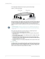
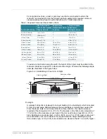
This section describes external antenna options and supported configurations for the
WLA632. Antenna Connectors 1, 2, and 3 are positioned on the top of the WLA632.
The connectors are labeled from left to right, when viewed from the front.
Antenna Connectors 4, 5, and 6 are positioned on the bottom of the WLA632. The
connectors are labeled accordingly, from left to right, when viewed from the front.
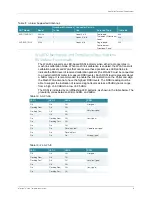
The table below lists the external user-accessible connectors that are required on the
WLA632. A watertight RJ45 is an acceptable alternative to the circular DIN connector
for the Ethernet interface.
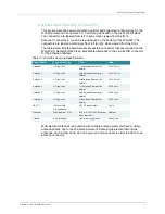
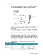
Multi-element antennas (an antenna with multiple antenna elements) have multiple
antenna cables, one for each antenna element. Some single-element omni stick
antennas, on the other hand, do not require an antenna cable in order to attach to an
antenna connector.
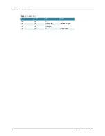
Table 10: WLA632 Antenna Specifications
Conn Name
Connector Type
Use
Label
Antenna 1
N-Type Jack
1st Antenna Element for
Radio 1
2.4GHZ Ant 1
Antenna 2
N-Type Jack
2nd Antenna Element for
Radio 1
2.4GHZ Ant 2
Antenna 3
N-Type Jack
3rd Antenna Element for
Radio 1
2.4GHZ Ant 3
Antenna 4
N-Type Jack
1st Antenna Element for
Radio 1
5GHZ Ant 4
Antenna 5
N-Type Jack
2nd Antenna Element for
Radio 1
5GHZ Ant 5
Antenna 6
N-Type Jack
3rd Antenna Element for
Radio 1
5GHZ Ant 6
48 VDC
IP67 multipin
DIN connector
48VDC power input
Pwr In
Ethernet
Weather-tight RJ45
802.3 10/100/1000 Ethernet
data input only
Ethernet
Ground
Anti-rotational
Lightning surge ground
Safety Gnd
Содержание WLA620
Страница 12: ...Table of Contents iv ...
Страница 30: ...WLA620 WLA622 and WLA632 Overview 18 Copyright 2012 Juniper Networks Inc ...
Страница 70: ...Installing and Connecting an Access Point 36 Copyright 2012 Juniper Networks Inc ...
Страница 90: ...Cables and Pinouts 6 Copyright 2012 Juniper Networks Inc ...


