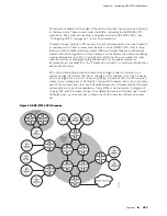
Figure 76: IPv6 VPN Services over IPv4 MPLS
The PE routers use an MP-BGP session over TCPv4 to advertise the IPv6 routes from
the CE devices to the remote PE routers. The IPv6 routes are advertised as labeled
VPNv6 routes with a BGP next hop set to the base tunnel endpoint destination address.
The next hop is formatted as an IPv4-mapped IPv6 address.
For IPv6 VPN services over an IPv4 backbone, the BGP next hop in the
MP_REACH_NLRI attribute contains a VPN-IPV6 address with the RD set to zero and
with the 16-byte IPv6 address encoded as an IPv4-mapped IPv6 address that contains
the IPv4 address of the advertising PE router. This IPv4 address must be routable in
the service provider’s backbone.
BGP Control Plane Behavior
The VPN service in Figure 76 on page 396 includes both CE 1 (VRF A) and CE 2 (VRF
B). The MPLS base tunnels are established to tunnel endpoints PE 1 and PE 2 at their
loopback interfaces. The loopback address for PE 1 is FFFF::1.1.1.1/128; for PE 2, it
is FFFF::2.2.2.2/128.
The BGP next hop that is advertised in the MP-BGP update includes the following:
■
A VPN-IPV6 address with the RD set to zero
■
The 16-byte IPv6 address encoded as an IPv4-mapped IPv6 address that contains
the IPv4 loopback address of the advertising PE router
The IPv4 IGP, such as OSPF, advertises the reachability of the loopback interfaces
on the PE routers. LDP binds label L2 to 1.1.1.1/32 on the P router.
CE–PE Behavior
CE 1 is connected to VRF A in PE 1 through an IPv4 interface. Similarly, CE 2 is
connected to VRF B in PE 2 through an IPv4 interface. You can alternatively run
OSPF to the CE devices over IPv6 links and redistribute the OSPF IPv6 routes into
BGP.
The MP-BGP sessions between the CE devices and the VRFs in the PE routers are
established over TCPv4. The AFI value is 2, indicating IPv6; the SAFI value is 1,
indicating unicast. CE 1 advertises IPv6 network 6001:0430::/48 to its MP-BGP peer
in VRF A. CE 2 advertises 6001:0431::/48 to its MP-BGP peer in VRF B. When it
receives the advertised prefix in VRF A, BGP adds 6001:0430::/48 to its BGP VPNv6
396
■
Intra-AS IPv6 VPNs
JUNOSe 11.1.x BGP and MPLS Configuration Guide
Содержание BGP
Страница 6: ...vi ...
Страница 8: ...viii JUNOSe 11 1 x BGP and MPLS Configuration Guide ...
Страница 37: ...Part 1 Border Gateway Protocol Configuring BGP Routing on page 3 Border Gateway Protocol 1 ...
Страница 38: ...2 Border Gateway Protocol JUNOSe 11 1 x BGP and MPLS Configuration Guide ...
Страница 234: ...198 Monitoring BGP JUNOSe 11 1 x BGP and MPLS Configuration Guide ...
Страница 236: ...200 Multiprotocol Layer Switching JUNOSe 11 1 x BGP and MPLS Configuration Guide ...
Страница 350: ...314 Example Traffic Class Configuration for Differentiated Services JUNOSe 11 1 x BGP and MPLS Configuration Guide ...
Страница 541: ... There is no no version See undebug ip mbgp Monitoring BGP MPLS VPNs 505 Chapter 5 Configuring BGP MPLS Applications ...
Страница 542: ...506 Monitoring BGP MPLS VPNs JUNOSe 11 1 x BGP and MPLS Configuration Guide ...
Страница 544: ...508 Layer 2 Services Over MPLS JUNOSe 11 1 x BGP and MPLS Configuration Guide ...
Страница 598: ...562 Multiple ATM Virtual Circuits over a Single Pseudowire Example JUNOSe 11 1 x BGP and MPLS Configuration Guide ...
Страница 610: ...574 Virtual Private LAN Service JUNOSe 11 1 x BGP and MPLS Configuration Guide ...
Страница 624: ...588 VPLS References JUNOSe 11 1 x BGP and MPLS Configuration Guide ...
Страница 648: ...612 VPLS Configuration Example with LDP Signaling JUNOSe 11 1 x BGP and MPLS Configuration Guide ...
Страница 680: ...644 Virtual Private Wire Service JUNOSe 11 1 x BGP and MPLS Configuration Guide ...
Страница 724: ...688 Monitoring MPLS Forwarding Table for VPWS JUNOSe 11 1 x BGP and MPLS Configuration Guide ...
Страница 725: ...Part 6 Index Index on page 691 Index 689 ...
Страница 726: ...690 Index JUNOSe 11 1 x BGP and MPLS Configuration Guide ...


