The ACX5400 router is designed to operate with a DC power supply that has a single, non-redundant, feed input. For
source redundancy, you must install two DC PSMs in the ACX5400; connect source (A) to one PSM and connect source
(B) to the second PSM. This configuration provides the commonly deployed A/B feed redundancy for the system.
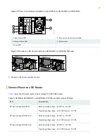
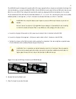
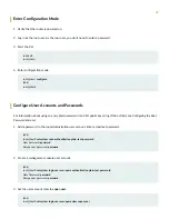
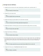
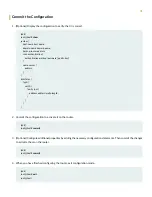
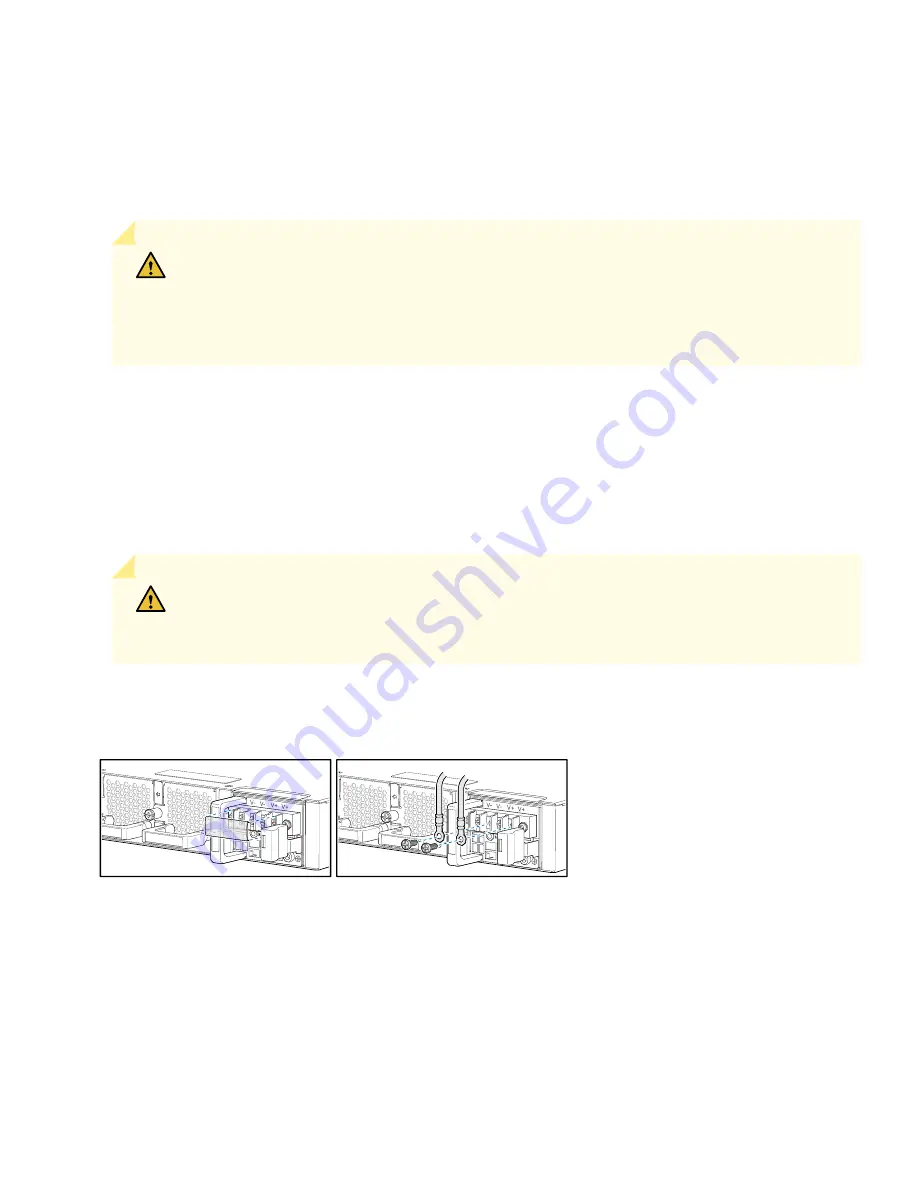
The terminal block of the PSM has four terminals labeled V+, V+, V–, and V– for connecting DC power source cables
labeled positive (+) and negative (–). The V+ terminals are shunted internally, as are the V— terminals.
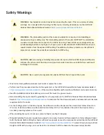
CAUTION:
The connection between each power source and PSM must include a 2-pole circuit
breaker.
Do not connect two sources to a single PSM because doing so can potentially cause circulating
current in feed wires whenever there is any difference in the voltage of the two sources.
a. Secure the ring lug of the positive (+) DC power source cable to the V+ terminal on the DC PSM.
b. Secure the ring lug of the negative (–) DC power source cable to the V– terminal on the DC PSM.
c. Tighten the screws on the PSM terminals until snug using the screwdriver. Do not overtighten—apply between
5 in-lb (0.56 Nm) and 6 in-lb (0.68 Nm) of torque to the screws.
CAUTION:
The V+ terminals are shunted internally, as are the V– terminals. The same polarity
terminal can be wired together from the same source to provide an additional current path in a
higher power chassis. Do not connect the terminals to different sources.
Figure 41: Connect a DC Power Cable to an ACX5400 Router
g100116
8. Replace the terminal block cover.
9. Close the input 2-pole circuit breaker.
24

