NOTE:
Ensure that you use a cable of 3 m or less in length for the 10-MHz and 1-PPS connectors.
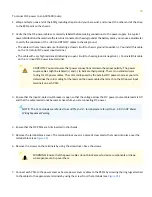
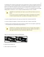
To connect the SMB to BNC coaxial cable to the external clocking input port:
1. Connect one end of the SMB to BNC coaxial cable to either the 1-PPS connector or the 10-MHz connector on the
router.
2. Connect the other end of the SMB to BNC coaxial cable to the 1-PPS or 10-MHz measurement equipment.
NOTE:
Ensure that the 10-MHz or 1-PPS source network equipment contains low-voltage complementary
metal oxide semiconductor (CMOS) or is compatible with low-voltage (3.3 V) transistor-transistor logic (TTL).
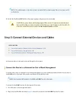
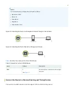
describes the clocking ports on the ACX5400 router.
Table 6: Clocking Port on the ACX5400 Router
Description
Callout
Label
GPS ports.
5
(See
.)
10M
PPS
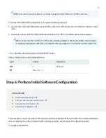
Step 6: Perform Initial Software Configuration
IN THIS SECTION
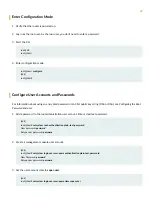
Configure User Accounts and Passwords | 29
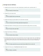
Configure System Attributes | 30
This procedure connects the router to the network but does not enable it to forward traffic. For complete information
about configuring the router to forward traffic, including examples, see the Junos OS configuration guides.
To configure the software:
28

