background image

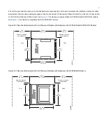
For service personnel to remove and install hardware components, and to accommodate the interface and power cable

bend radius, there must be adequate space at the front and rear of the router. Allow at least 24 in. (61 cm) of space both
at the front and the rear of the router. See

Figure 12

for clearance requirements in ACX5448 and ACX5448-D routers

and

Figure 13

for clearance requirements in ACX5448-M routers.

Figure 12: Clearance Requirements for Airflow and Hardware Maintenance for ACX5448 and ACX5448-D Routers

g100124

21.81 in.

( 55.41 cm)

19 in.

(48.2 cm)

17.26 in.

(43.84 cm)

Ports

FRUs

24 in.

(61 cm)

Clearance required

for maintenance

24.0 in.

(61 cm)

Clearance required

for maintenance

20 .29 in.

( 51.53 cm)

Figure 13: Clearance Requirements for Airflow and Hardware Maintenance for ACX5448-M Routers

g100706

25.50 in.

(64.75 cm)

19 in.

(48.2 cm)

17.26 in.

(43.84 cm)

Ports

FRUs

24 in.

(61 cm)

Clearance required

for maintenance

24.0 in.
(61 cm)

Clearance required

for maintenance

24.0 in.

(61.0 cm)

9

Содержание ACX5448

Страница 1: ...11 Step 3 Connect the Grounding Cable 16 Step 4 Connect Power Cables 18 Step 5 Connect External Devices and Cables 25 Step 6 Perform Initial Software Configuration 28 Safety Warnings 32 Compliance St...

Страница 2: ...ACX5400 control plane We ship these routers with redundant fans and redundant power supply modules PSMs You can order the routers with front to back airflow airflow out or AFO or back to front airflo...

Страница 3: ...ther with DC power Figure 2 Rear View of the AC Powered ACX5448 Router g100101 2 1 1 2 1 Fan modules Power supply modules AC Figure 3 Rear View of the DC Powered ACX5448 Router g100102 2 1 1 2 1 Fan m...

Страница 4: ...P2 DCO transceivers NOTE One QSFP28 port port 36 and one CFP2 DCO port port 38 can operate as multiplexer ports Figure 4 shows the front of the ACX5448 D router Figure 4 Front View of the ACX5448 D Ro...

Страница 5: ...s also support 40 Gbps speed when you use QSFP optics You can then channelize each of these 40 Gbps ports into four 10 Gbps interfaces using breakout cable and channelization configuration NOTE The AC...

Страница 6: ...e ACX5448 router and Figure 11 shows the ESD point on the ACX5448 D and ACX5448 M routers CAUTION Before removing or installing components attach an ESD strap to an ESD point and wrap and fasten the o...

Страница 7: ...00 Router IN THIS SECTION Rack Requirements for ACX5400 Routers 7 Router Clearance Requirements 8 Router Cooling and Airflow Requirements 10 Tools Required to Prepare the ACX5400 Router for Installati...

Страница 8: ...n 48 26 cm from outer edge to outer edge Use approved wing devices to narrow the opening between the rails as required Ensure that the rack rails are spaced widely enough to accommodate the router cha...

Страница 9: ...s in ACX5448 M routers Figure 12 Clearance Requirements for Airflow and Hardware Maintenance for ACX5448 and ACX5448 D Routers g100124 21 81 in 55 41 cm 19 in 48 2 cm 17 26 in 43 84 cm Ports FRUs 24 i...

Страница 10: ...hausted out of the chassis The fan modules and the power supply modules PSMs are available in both AFO and AFI variants Figure 14 and Figure 15 show the airflow through the two router models For the c...

Страница 11: ...blades to the rack not provided Appropriate screwdriver for the mounting screws not provided Two power cords with plugs appropriate for your geographical location provided RJ 45 cable and RJ 45 to DB...

Страница 12: ...erson on each side hold on to the bottom of the chassis and carefully lift it so that the mounting rails contact the rack rails 6 Carefully slide the chassis with the rails attached on to the rack rai...

Страница 13: ...bracket holes aligned with the rack starting from the bottom and secure them tightly Figure 22 Figure 23 and Figure 24show the router fully secured to the front rails of the four post rack Figure 22 A...

Страница 14: ...the end of the blades contact the rack rails see Figure 25 for the ACX5448 router Figure 26 for the ACX5448 D router and Figure 27 for the ACX5448 M router The mounting blades are movable You can adj...

Страница 15: ...the alignment of the chassis If you ve installed the chassis properly in the rack all the mounting screws on one side of the rack are aligned with the mounting screws on the opposite side and the rou...

Страница 16: ...c interference EMI requirements and to ensure proper operation you must ground the router properly before connecting power Figure 31 Figure 32 and Figure 33 show the grounding points on ACX5400 router...

Страница 17: ...10 10A L or equivalent not provided The grounding lug accommodates 12 AWG 2 5 mm stranded wire The grounding cable that you provide for the chassis must be the same size or heavier than the input wire...

Страница 18: ...grounding cable lug with the screws The holes are sized to accommodate 10 32 pan head screws 7 Dress the grounding cable and verify that it does not touch or block access to router components and tha...

Страница 19: ...ating range 100 240 VAC AC input voltage To connect AC power to an ACX5448 router 1 Wrap and fasten one end of the ESD grounding strap around your bare wrist and connect the other end of the strap to...

Страница 20: ...5 2 Ejector lever Output status LED 3 Fault LED 5 Press the small tab on the retainer strip to loosen the loop Slide the loop until you have enough space to insert the power cord coupler into the inle...

Страница 21: ...pply 3 Connect the power cord to the source power supply Insert the coupler end of the power cord into the AC power cord inlet on the AC power supply faceplate NOTE Each PSM must be connected to a ded...

Страница 22: ...Power to a DC Router Table 3 gives the DC power system input voltage for ACX5400 routers Table 3 ACX5448 ACX5448 D and ACX5448 M DC Power System Input Voltage Specification Item Rated operating voltag...

Страница 23: ...standard color coding for DC power cables The color coding used by the external DC power source at your site determines the color coding for the leads on the power cables that attach to the DC power...

Страница 24: ...so can potentially cause circulating current in feed wires whenever there is any difference in the voltage of the two sources a Secure the ring lug of the positive DC power source cable to the V term...

Страница 25: ...to a Network for Out of Band Management 25 Connect the Router to a Console Device 26 Connect the Router to External Clocking and Timing Devices 27 All the connections to the router are made through th...

Страница 26: ...console to configure and manage the router connect it to the appropriate CON port on the router The console port is used to connect a laptop or console terminal to configure the router see Figure 43...

Страница 27: ...igure 44 Connecting the Router Directly to a Management Console g020570 Laptop CPU To Console Port CON Table 5 describes the console port for the ACX5400 router Table 5 Console Port on the ACX5400 Rou...

Страница 28: ...e semiconductor CMOS or is compatible with low voltage 3 3 V transistor transistor logic TTL Table 6 describes the clocking ports on the ACX5400 router Table 6 Clocking Port on the ACX5400 Router Desc...

Страница 29: ...string DSA or RSA see Configuring the Root Password and user 1 Add a password to the root administration user account Enter a cleartext password edit root host set system root authentication plain tex...

Страница 30: ...unning edit root host set system backup router address 5 Configure the IP address of a DNS server edit root host set system name server address 6 Optional Configure the static routes to remote subnets...

Страница 31: ...key name server address interfaces fxp0 unit 0 family inet address address prefix length 2 Commit the configuration to activate it on the router edit root host commit 3 Optional Configure additional...

Страница 32: ...all or replace the router Perform only the procedures described in this quick start or the ACX5448 Universal Metro Router Hardware Guide at https www juniper net documentation Other services should be...

Страница 33: ...und wire first and disconnect it last Do not work on the system or connect or disconnect cables during electrical storms Before working on equipment that is connected to power lines remove jewelry inc...

Страница 34: ...his is a Class A product In a domestic environment this product might cause radio interference in which case the user might be required to take adequate measures Israel Translation from Hebrew Warning...

Страница 35: ...ates uses and can radiate radio frequency energy and if not installed and used in accordance with the instruction manual might cause harmful interference to radio communications Operation of this equi...

Страница 36: ...equest and issues an RMA number for return of the component Juniper Networks the Juniper Networks logo Juniper and Junos are registered trademarks of Juniper Networks Inc in the United States and othe...

Отзывы: