KNX Facility-Panel
Ref.-no.: FP 701 CT
5. Information for qualified electricians
5.1. Installation and electrical connection
DANGER
Electric shock in case of accidental contact with live parts.
Electric shocks may be fatal. Always clear power cables and
cover active parts in the surroundings before working on the
device.
Installing and connecting the device3
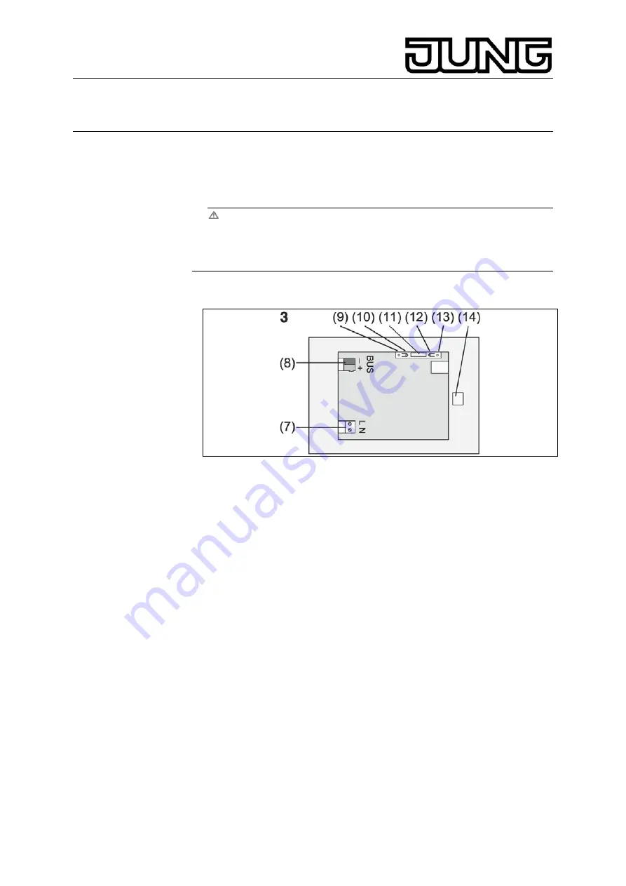
Figure 3, bottom side
(7) Mains voltage terminal
(8) Bus connection
(9) Programming LED
(10) Programming key
(11)
Ext
. terminal for future upgrades, e.g. external pushbutton
(12) Reset key
(13) Reset LED
(14) USB Terminal
Installation in flush-mounting box (figure 4, 17)
L
Programming key and LED are accessible only from the bottom of the
device. If possible, load the physical address into the device before
the final installation (startup).
Install the flush-mounting box in the correct position – horizontally or
vertically aligned – in the wall. Horizontal installation: Arrow
OBEN TOP
points upwards. Vertical installation: Arrow
OBEN TOP
points to the left.
Pull bus and 230 V lines through the appropriate bushings.
Connect mains voltage AC 230 V to terminal (7).
Connect bus line to terminal (8).
9


