


– 69 –
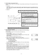
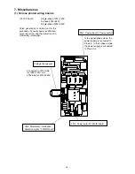
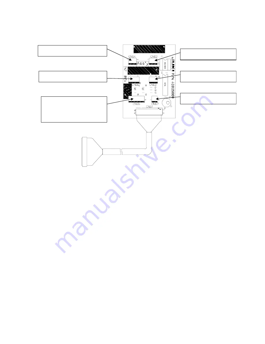
6) INT board
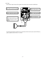
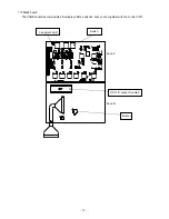
The INT board repeats the head sensor signals and transfers the head model data to the MAIN board.
The head model type (Memory switch No. 241), corrected value of the active tension, the number of stitches for
grease-up (Memory switch No. 245), etc. are stored.
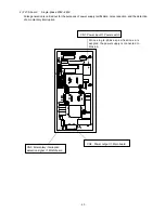
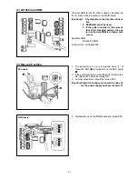
CN64: Presser bar lifter origin (black)
CN65: Needle thread clamp origin
Needle thread clamp operation
(yellow)
CN66: Thread trimmer operation (red)
CN67: Fall switch (red)
CN63: Y feed origin (yellow)
CN62: X feed origin (red)
Face F
Содержание LK-1900A
Страница 20: ... 16 10 Hook adjustment Standard Adjustment 0mm 0mm 7 5mm 0 05 0 1mm For DPX5 For DPX17 ...
Страница 87: ... 83 Grease Grease 3 Thread tension area 4 Thread trimmer area Grease Juki Grease A Grease Grease Juki Grease A ...
Страница 88: ... 84 Grease Grease Grease Templex N2 Grease Templex N2 Grease Grease Grease Grease Grease 5 Feed area ...
Страница 90: ... 86 Grease Grease Grease Grease Grease 8 Needle thread clamp mechanism area ...
Страница 91: ... 87 Grease Grease A Grease Grease Grease Grease 9 LK 1901A relations ...
Страница 92: ... 88 10 LK 1903A relations Grease Grease ...
Страница 114: ... 111 12 Circuit diagrams 1 Block diagram A ...
Страница 115: ... 112 2 Power supply circuit diagram A ...
Страница 116: ... 113 3 Power supply circuit diagram B ...
Страница 117: ... 114 4 Power supply circuit diagram C ...
Страница 118: ... 115 5 Servo motor circuit diagram ...
Страница 119: ... 116 6 Sensor pedal VR circuit diagram ...
Страница 120: ... 117 7 MAIN PANEL board circuit diagram ...
Страница 121: ... 118 8 Motor solenoid circuit diagram Thread trimmer Lifting the work clamp foot motor ...