


– 108 –
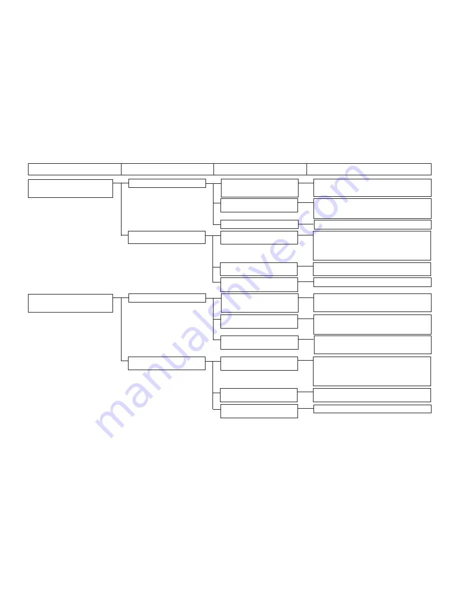
20. Error E910
20-1) Irregular motor rotations
1-A) There are irregularities in
Check the mechanism and look for the section that
Work clamp foot origin retrieval
the mechanism, such as
is particularly overloaded or whether screws are
error
overloading, etc.
loose.
1-B) Motor leads are broken.
Disconnect CN44 (red) of the MAIN board and check
The motor is out of order.
the motor resistance. [See the Motor / Solenoid
Circuit Diagram.] Replace the motor.
1-C) The MAIN board is out of order.
Replace the MAIN board.
20-2)No sensor signal entry
2-A) The sensor is out of order or
Check whether the sensor lamp is turned ON/OFF
Use of Test Mode CP-1 or CP-2
broken.
when a metallic plate is moved closer to or separated
from the sensor plane. In the case of no lamp ON/
OFF, the sensor is broken or the connector block is
disconnected.
2-B) The INT board connector is
Check the connection of CN64 (black) of the INT
disconnected.
board
2-C) Sensor mounting position is
Check and correct the sensor mounting position.
inadequate.
21. Error E913
21-1) Irregular motor rotations
1-A) There are irregularities in
Check the mechanism and look for the section that
Needle thread clamp origin retrieval
the mechanism, such as
is particularly overloaded or whether screws are
error
overloading, etc.
loose.
1-B) Motor leads are broken.
Disconnect CN45 (yellow) of the MAIN board and
The motor is out of order.
check the motor resistance. [See the Motor/
Solenoid Circuit Diagram.] Replace the motor.
1-C) The driver circuit has no
Check F3 of the SDC board. After confirming the
power supply. (24V)
presence of short-circuiting in the 24V system, replace
the fuse.
21-2)No sensor signal entry
2-A) The sensor is out of order or
Check whether the sensor lamp is turned ON/OFF
Use of Test Mode CP-1 or CP-2
broken.
when a metallic plate is moved closer to or separated
from the sensor plane. In the case of no lamp ON/
OFF, the sensor is broken or the connector block is
disconnected.
2-B) The INT board connector is
Check the connection of CN65 (yellow) of the INT
disconnected.
board
2-C) Sensor mounting position is
Check and correct the sensor mounting position.
inadequate.
Trouble
Cause (1)
Cause (2)
Check and corrective measures
Содержание LK-1900A
Страница 20: ... 16 10 Hook adjustment Standard Adjustment 0mm 0mm 7 5mm 0 05 0 1mm For DPX5 For DPX17 ...
Страница 87: ... 83 Grease Grease 3 Thread tension area 4 Thread trimmer area Grease Juki Grease A Grease Grease Juki Grease A ...
Страница 88: ... 84 Grease Grease Grease Templex N2 Grease Templex N2 Grease Grease Grease Grease Grease 5 Feed area ...
Страница 90: ... 86 Grease Grease Grease Grease Grease 8 Needle thread clamp mechanism area ...
Страница 91: ... 87 Grease Grease A Grease Grease Grease Grease 9 LK 1901A relations ...
Страница 92: ... 88 10 LK 1903A relations Grease Grease ...
Страница 114: ... 111 12 Circuit diagrams 1 Block diagram A ...
Страница 115: ... 112 2 Power supply circuit diagram A ...
Страница 116: ... 113 3 Power supply circuit diagram B ...
Страница 117: ... 114 4 Power supply circuit diagram C ...
Страница 118: ... 115 5 Servo motor circuit diagram ...
Страница 119: ... 116 6 Sensor pedal VR circuit diagram ...
Страница 120: ... 117 7 MAIN PANEL board circuit diagram ...
Страница 121: ... 118 8 Motor solenoid circuit diagram Thread trimmer Lifting the work clamp foot motor ...