


– 68 –
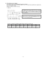
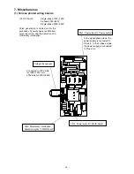
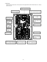
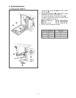
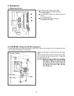
5) MAIN board
Overall controls are carried out, such as pulse motor driving for shafts, control of active tension, etc., memory
switch control, etc.
1
CN32: For the SDC board
CN34: For the panel
CN38: For the INT board (head)
U11: LK-1900 PROM
27C256
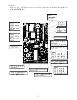
CN49: Temporary
stop (for OP)
CN45: Needle
thread clamp PM
(yellow)
CN47: Material
drawing MG
(LK-1901A)
CN46: For air
(for OP)
CN36: For BR35
CN31: Power
←
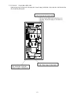
SDC board
+5V, +12V, +24V, +33V, +85V
CN42: X feed PM (white)
CN43: Y feed PM (blue)
CN41: Foot pedal
(for OP)
CN44: Clamp PM
(red)
CN39: Active tension
CN40: Pedal sensor
Содержание LK-1900A
Страница 20: ... 16 10 Hook adjustment Standard Adjustment 0mm 0mm 7 5mm 0 05 0 1mm For DPX5 For DPX17 ...
Страница 87: ... 83 Grease Grease 3 Thread tension area 4 Thread trimmer area Grease Juki Grease A Grease Grease Juki Grease A ...
Страница 88: ... 84 Grease Grease Grease Templex N2 Grease Templex N2 Grease Grease Grease Grease Grease 5 Feed area ...
Страница 90: ... 86 Grease Grease Grease Grease Grease 8 Needle thread clamp mechanism area ...
Страница 91: ... 87 Grease Grease A Grease Grease Grease Grease 9 LK 1901A relations ...
Страница 92: ... 88 10 LK 1903A relations Grease Grease ...
Страница 114: ... 111 12 Circuit diagrams 1 Block diagram A ...
Страница 115: ... 112 2 Power supply circuit diagram A ...
Страница 116: ... 113 3 Power supply circuit diagram B ...
Страница 117: ... 114 4 Power supply circuit diagram C ...
Страница 118: ... 115 5 Servo motor circuit diagram ...
Страница 119: ... 116 6 Sensor pedal VR circuit diagram ...
Страница 120: ... 117 7 MAIN PANEL board circuit diagram ...
Страница 121: ... 118 8 Motor solenoid circuit diagram Thread trimmer Lifting the work clamp foot motor ...