background image

– 10 –

1)  Adjust the amount of oil supplied to the thread 

take-up and needle bar crank 

 by turning adjust 

pin 

.

2)  The minimum amount of oil is reached when 

marker dot 

A

 is brought close to needle bar 

crank 

 by turning the adjust pin in direction 

B

.

3)  The maximum amount of oil is reached when 

marker dot 

A

 is brought to the position just 

opposite from the needle bar crank by turning the 
adjust pin in direction 

C

.

Minimum

Maximum

A

B

C

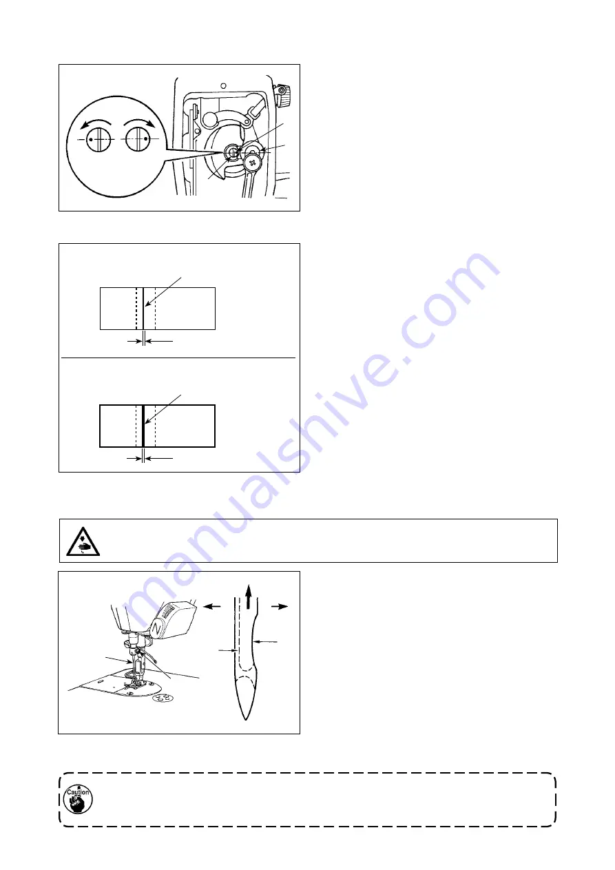
(6) Sample showing the appropriate amount of oil supplied to the face plate parts

1)  The state given in the figure shows


the appropri-

ate amount of oil (oil splashes). It is necessary to 

finely adjust the amount of oil in accordance with 

the sewing processes. However, do not exces-
sively increase/decrease the amount of oil in the 
hook. (If the amount of oil is too small, the face 
plate parts will be hot or seize. If the amount of oil 
is too much, the sewing product may be stained 
with oil.)

2) 

Check the oil amount (oil splashes) three times 

(with three sheets of paper).

Use the specified needle for the machine. Use the 

proper needle in accordance with the thickness of 
thread used and the kinds of the materials. 
1)  Turn the handwheel until the needle bar reaches 

the highest point of its stroke.

2)  Loosen screw 

, and hold needle 

 with its 

indented part 

A

 facing exactly to the right in 

direction 

B

3)  Insert the needle fully into the hole in the needle 

bar in the direction of the arrow until the end of 
hole is reached. 

4)  Securely tighten screw 

5)  Check that long groove 

C

 of the needle is facing 

exactly to the left in direction 

D

.

When polyester filament thread is used, if the indented part of the needle is tilted toward opera

-

tor's side, the loop of thread becomes unstable. As a result, hangnail of thread or thread break-

age may occur. For the thread that such phenomenon is likely to occur, it is effective to attach 

the needle with its indented part slightly slanting on the rear side.

11. Attaching the needle

WARNING :

Be sure to turn the power OFF before the following work in order to prevent personal injury due to 

unintentional starting of the sewing machine.

Splashes of oil from the thread take-up lever

1 mm

Appropriate amount of oil (large)

Appropriate amount of oil (small)

2 mm

Splashes of oil from the thread take-up lever

(5) Adjusting the amount of oil supplied to the face plate parts

C

D

B

A

Содержание DDL-8100B-7 Series

Страница 1: ...I DDL 8700B 7 INSTRUCTION MANUAL ...

Страница 2: ... Tilt of the feed dog 15 24 Adjusting the feed timing 15 25 Counter knife 16 26 Pedal pressure and pedal stroke 16 27 Adjustment of the pedal 17 28 Marker dots on the handwheel 17 III FOR THE OPERATOR 18 1 Operating procedure of the sewing machine 18 2 Setting procedure of the machine head 19 3 Operation panel built in the machine head 20 4 Operating procedure of the sewing pattern 21 5 One touch ...

Страница 3: ...nt continuous emission sound pressure level LpA at the workstation A weighted value of 79 5 dB Includes KpA 2 5 dB according to ISO 10821 C 6 2 ISO 11204 GR2 at 4 000 sti min DDL 8700BS 7 DDL 8700BH 7 Application Light to Medium weight materials Heavy weight materials S type H type Light weight materials Heavy weight materials Schematic drawing of the applicable range Max sewing speed 5 000 sti mi...

Страница 4: ...om surface depth 20 Drill a hole at the time of set up B Installing position of drawer stopper on the reverse side C ø18 drilled hole D 3xø13 drilled hole E 2xø3 5 depth 10 F 2xø3 5 depth 10 G ø40 0 5 drilled hole H ø16 depth 30 I C1 5 to C2 5 hinge side only ...

Страница 5: ...itting the nail and the other two rubber cushion seats on the hinge side B are fixed by using a rubber based adhesive Then oil pan is placed 5 Fit knee lifter pressing rod Fit hinge into the opening in the machine bed and fit the machine head to table rubber hinge before placing the machine head on cushions on the four corners 6 Securely attach head support rod to the table until it goes no furthe...

Страница 6: ...onnector can break but also it can start abruptly inviting the risk of personal injury To prevent personal injury caused by maloperation be sure to lock the connector with lock As for the details of handling respective devices read carefully the Instruction Manuals supplied with the devices before handling the devices Do not insert the power plug into the wall outlet Check to be sure that the powe...

Страница 7: ...ure to prepare the power plug which conforms to the safety stan dard 2 Be sure to connect the ground lead green yellow to the grounding side WARNING To protect against possible personal injury due to abrupt start of the machine be sure to start the following work after turning the power off and a lapse of 5 minutes or more 3ø 200 240V Black Red White Green Yellow ground wire AC 200 240V AC 220 240...

Страница 8: ...on of A Decrease To the direction of B Increase 6 Winding the bobbin thread 6 In case that the bobbin thread is not wound evenly on the bobbin loosen screw and adjust the height of bobbin thread tension It is the standard that the center of the bobbin is as high as the center of thread tension disk Adjust the position of thread tension disk to the direction of D when the winding amount of the bobb...

Страница 9: ...ver 10 mm be sure that the bottom end of needle bar in its lowest position does not hit presser foot WARNING Be sure to turn the power OFF before the following work in order to prevent personal injury due to unintentional starting of the sewing machine 7 Adjusting the height of the knee lifter 8 Installing the thread stand 1 Assemble the thread stand unit and insert it in the hole in the machine t...

Страница 10: ...on 1 Before starting the sewing machine fill oil pan with JUKI MACHINE OIL 7 up to HIGH mark A 2 Add oil before the oil surface comes down to reach the LOW mark B 3 When you operate the machine after lubrication you will see splashing oil through oil sight window if the lubrication is adequate 4 Note that the amount of the splashing oil is unre lated to the amount of the lubricating oil 1 When you...

Страница 11: ...y 30 seconds to check the amount of oil in the hook A B 2 Adjusting the amount of oil oil spots in the hook 3 Sample showing the appropriate amount of oil in the hook 2 mm Splashes of oil from the hook Amount of oil oil splashes confirmation paper Position to confirm the amount of oil oil splashes Oil splashes confirmation paper 25 mm 70 mm 4 Confirmation of the amount of oil supplied to the face ...

Страница 12: ...ordance with the thickness of thread used and the kinds of the materials 1 Turn the handwheel until the needle bar reaches the highest point of its stroke 2 Loosen screw and hold needle with its indented part A facing exactly to the right in direction B 3 Insert the needle fully into the hole in the needle bar in the direction of the arrow until the end of hole is reached 4 Securely tighten screw ...

Страница 13: ...llimeters reference value 1 Turn stitch length dial in the direction of the arrow and align the desired number to marker dot A on the machine arm 1 Loosen nut As you turn presser spring regula tor clockwise in direction A the presser foot pressure will be increased 2 As you turn the presser spring regulator count er clockwise in direction B the pressure will be decreased 3 After adjustment tighten...

Страница 14: ...r bar 17 Threading the machine head WARNING Be sure to turn the power OFF before the following work in order to prevent personal injury due to unintentional starting of the sewing machine WARNING Be sure to turn the power OFF before the following work in order to prevent personal injury due to unintentional starting of the sewing machine In the case the thread clamp is used ...

Страница 15: ...ut by the thread take up 3 Normally thread guide is positioned in a way that marker line C is aligned with the center of the screw 1 Adjusting the needle thread tension 1 The length of thread remaining at the needle tip after thread trimming is shortened by turning ten sion regulating nut No 1 clockwise in direction A 2 It is lengthened by turning the nut counterclock wise in direction B 3 The nee...

Страница 16: ...ottom end of needle bar lower bushing 4 After making the adjustments mentioned in the above steps align hook blade point with the center of needle Provide a clearance of 0 04 mm to 0 1 mm reference value between the needle and the hook then securely tighten set screws in the hook If the clearance between the blade point of hook and the needle is smaller than the specified value the blade point of ...

Страница 17: ... the feed bar shaft is aligned with marker dot B on feed rocker 2 To tilt the feed dog with its front up in order to prevent puckering loosen the setscrew and turn the feed bar shaft 90 in the direction of the arrow using a screwdriver 3 To tilt the feed dog with its front down in order to prevent uneven material feed turn the feed bar shaft 90 in the opposite direction from the arrow Whenever the...

Страница 18: ...spring on the left side 3 The pressure increases when you hook the spring on the right side 2 Adjusting the pressure required to depress the back part of the pedal 1 This pressure can be adjusted using regulator screw 2 The pressure increases as you turn the regulator screw in 3 The pressure decreases as you turn the screw out 3 Adjusting the pedal stroke 1 The pedal stroke increases when you inse...

Страница 19: ... the length of connecting rod 27 Adjustment of the pedal WARNING Be sure to turn the power OFF before the following work in order to prevent personal injury due to unintentional starting of the sewing machine 28 Marker dots on the handwheel Red White The upper stop position of the needle bar is reached when marker dot on the cover is aligned with white marker dot on the handwheel The operating tim...

Страница 20: ...feed switch is pressed the sewing machine performs reverse feed stitching 4 Reverse feed stitching at the beginning of sewing reverse feed stitching at the end of sewing and various sewing patterns can be set on built in panel of the machine head b The machine runs at high sewing speed when you further depress the front part of the pedal If the automatic reverse feed stitching has been preset the ...

Страница 21: ...95 2 Press switch 3 Press and switches to select the type of the machine head 87bS Light to Medium weight materials 87bH Heavy weight materials 4 After the selection of the type of the machine head press switch to confirm the se lection The settings are automatically initialized according to the type of the machine head ...

Страница 22: ...e Used to change over the automatic double reverse feed stitching at the end of sewing between enable and disable Used to change over the soft start func tion between enable and disable Used to change over the reverse feed stitching pattern between enable and disable Used to change over the needle bar stop position at the time of stopping sewing between up and down Used to change over the overlapp...

Страница 23: ...n can be programmed A Number of stitches of normal stitching setting 0 to 15 stitches B Number of stitches of reverse stitching setting 0 to 15 stitches C Number of stitches of normal stitching setting 0 to 15 stitches D Number of times of repetition 0 to 15 times 1 When process D is set to 5 times the sewing is repeated as A B C B C 2 The number which exceeds 9 is indicated as follows A 10 b 11 c...

Страница 24: ...d the number of stitches of process E can be set by pressing switch again 3 The number of stitches 0 to 999 for the constant dimension stitching can be selected by pressing and switches Label sewing 1 Press switch to select the label sewing When the selection is effective LED Ⓗ lights up Every time switch is pressed the indication of processes E to H will be changed over 2 Display the target proce...

Страница 25: ...tting items 1 Press and switches to select the setting item Example niP 2 Press switch The current set value is displayed Example on 3 Press and switches to change the set value Example oFF 4 Press switch to confirm the set value 5 Press switch to finish the one touch setting 1 In the case the function setting n is selected operation using switch cannot be carried out Once the setting of the funct...

Страница 26: ...n the left are used for changing the number in the fast feed mode 3 Press switch to change the setting The indication is changed to the set value The figure shows the case where the set value is changed from the indication n 96 to 4000 set value by pressing switch 4 Press and switches to change the set value 5 Press switch to confirm the set value 6 The display returns to the state described in 1 ...

Страница 27: ...laced Number of stitches counting function LED Ⓖ lights up The number of stitches is counted from the start of sewing until thread trimming is carried out Sewing counting function 1 Counted value is indicated on display section A 2 The value on the counter can be changed by pressing and switches 3 The value on the counter is reset to 0 zero by pressing switch 4 The sewing counting function setting...

Страница 28: ...ut 2 The value on the counter is reset to the initial value by pressing switch 3 In this state the initial value can be changed by pressing and switches Number of stitches counting function 1 The number of stitches is automatically counted from the start of sewing until thread trimming is carried out 2 Once thread trimming is carried out the value on the counter is reset to 0 zero Ⓒ Ⓐ Ⓑ Ⓓ Ⓕ ...

Страница 29: ...does not operate 1 Thread clamp operates 0 1 1 21 Function of automatic presser foot lifting at pedal s neutral position Function of lifting presser foot when the pedal is in neutral position 0 Function of neutral automatic presser lifting is not operative 1 Selection of function of neutral presser lifting 0 1 0 22 Needle up down correc tion switch changeover function Function of the needle up dow...

Страница 30: ...of sewing Compensation of releasing the solenoid for reverse feed stitching when reverse feed stitching at the start of sewing is performed 36 to 36 10 The setting differs with the machine head 37 53 Compensation of solenoid off timing of reverse feed stitching at the end of sewing Compensation of releasing the solenoid for reverse feed stitching when reverse feed stitching at the end of sewing is...

Страница 31: ...ot reduced 1 Speed is reduced 0 1 1 39 93 Function added to nee dle up down compensat ing switch Operation of needle up down compensating switch is changed after turning ON the power or thread trimming 0 Normal Needle up down compensating stitching only 1 One stitch compensating stitching is performed only when aforemen tioned changeover is made Upper stop upper stop 0 1 0 40 95 Head selection fun...

Страница 32: ... production support function stops counting is set 0 The sewing counter stops counting when a value is entered to the sewing counter using the optional input output function 1 to 20 The sewing counter stops counting according to the preset number of times of thread trimming 0 to 20 1 186 Soft start resetting angle An angle at which the start is reset is set This setting is enabled when the thread ...

Страница 33: ... function reduces flickering of the hand lamp at the start of sewing n 5 0 Flicker reducing function is ineffective 1 Flicker reducing function is effective Caution When the flicker reducing function is set at the Flicker reducing function is effective the startup speed of the sewing machine decreases Selection of the optional input output function Function setting No 12 For some of the input outp...

Страница 34: ...tting procedures 1 through 3 2 Press switch 3 Select a port for example i1 to be set by pressing switches 4 Press switch 5 Select a function for example Trm by pressing switches 6 Press switch 7 Activate the selected function by pressing switches 8 Press switch 9 Finish function setting by pressing switch n 2 1 1 i 1 i T b M T r L 0 L 0 to H 0 0 i ...

Страница 35: ...rohibited 11 LSSW Low speed command input This function works as low speed switch for standing sewing machine 12 HSSW High speed command input This function works as high speed switch for standing sewing machine 13 USW Needle lifting function UP stop motion is performed when switch is pressed during DOWN stop 14 bT Reverse feed stitching switch input Reverse feed stitching is output as long as the...

Страница 36: ...r output State of cancel of reverse feed stitching at start end is output 8 AUbT Sewing start end cancellation addi tion monitor output State of cancel or addition of automatic reverse feed stitching is output 9 SSTA Sewing machine stop state output Sewing machine stop state is output 10 CooL Needle cooler output Output for needle cooler 11 bUZ Buzzer output It is output when the bobbin counter se...

Страница 37: ... functions only when the sewing machine is running 1 ON Operative when the sewing machine stops Reverse feed stitching on the way functions both when the sewing machine is running and stops Caution Either condition is operative when the sewing machine is running Function setting No 33 Thread trimming is performed when reverse feed stitching on the way is com pleted n 3 3 0 OFF Without thread trimm...

Страница 38: ...ks either when the sewing machine stops or when the sewing machine is running It is especially effective when the sewing machine is used as the stand ing work machine Sewing speed of one shot stitching Function setting No 38 This function can set by the pedal operation of one time the sewing speed of one shot stitching when the sewing machine continues stitching until completing the number of stit...

Страница 39: ...off timing of solenoid for reverse feed stitching at the start of sewing Function set ting No 52 Off timing of solenoid for reverse feed stitching at the start of sewing can be compensated by the unit of angle n 2 5 Adjusting range 36 to 36 1 10 Set value Compensation angle Number of stitches of compensation 36 360 1 18 180 0 5 0 0 0 18 180 0 5 36 360 1 Compensation of off timing of solenoid for r...

Страница 40: ...d It is therefore necessary to adjust the length of thread remaining after thread trimming properly Function of holding predetermined upper lower position of the needle bar Function setting No 58 When the needle bar is in the upper position or in the lower position this function holds the needle bar by applying a brake slightly n 8 5 0 OFF Not provided with the function of holding predetermined up...

Страница 41: ...etting No 49 is set longer when lowering the presser foot by depressing the pedal n 9 4 Setting range 0 to 500 ms 10 ms Step n 0 7 0 Function of soft down of presser foot is not operative Presser foot is rapidly lowered 1 Selection of function of soft down of presser foot Function of reducing speed of reverse feed stitching at the start of sewing Function setting No 92 Function to reduce speed at ...

Страница 42: ...e stitch operation can be performed only when the needle up down compensating switch is pressed at the time of upper stop immediately after turning ON the power switch or upper stop immediately after thread trimming n 3 9 0 Normal Only needle up down compensating stitching operation 1 One stitch compensating stitching operation upper stop upper stop is performed only when aforementioned changeover...

Страница 43: ... pedal according to the below stated How to adjust the pedal If you place your foot or any object on the pedal the pedal will not operate properly Operate the pedal with nothing placed on it a Check the digit which flashes on and off to determine the direction of pedal dislocation In the case the pedal sensor neutral position is displaced toward the front part of the pedal In the case the pedal se...

Страница 44: ...tive 3 Turn OFF the power switch and turn ON the power switch again to return to the normal mode 4 Repeat the operation 1 to 3 and display is turned to FL of Then the function of auto lifter does not work Automatic presser lifter is provided AK is provided Automatic presser lifter is not provided 1 To perform re turning ON of the power be sure to perform after the time of one second or more has pa...

Страница 45: ...ling the key lock function Display section A 1 Referring to the explanation of III 6 Setting of functions p 24 select function setting n 95 Then press switch 2 Press and hold switch 3 The buzzer sounds after approximately one sec ond and the setting data returns to the standard setting value Do not turn OFF the power on the way of initializing operation Program of the main unit may be broken 4 Tur...

Страница 46: ...proce dure 16 Height adjustable one touch type reverse stitching switch Height of touch back switch is adjustable For the process during which touch back switch is not used the material on the sewing machine can be handled with ease by increasing the height of the switch How to adjust the height The switch height can be adjusted along the bracket by loosening screw WARNING In order to protect agai...

Страница 47: ... pulley of the machine head by hand until the main shaft reference signal is detected At this time the degree of an angle from the main shaft reference signal is displayed on the display section A The value is the reference value 3 In this state align the white dot of the hand wheel with the concave of the pulley cover as shown in the figure 4 Press switch to finish the adjustment work At this tim...

Страница 48: ...auto lifter device is not con nected to connector CN37 Connect the cord properly Touch back switch fails to work Presser foot is going up by auto liter device Operate the switch after the presser foot lowered Auto lifter device is not attached How ever auto lifter function is ON Select Automatic presser lifter is not provided when auto lifter device is not attached Sewing machine fails to run Moto...

Страница 49: ...03 Semicircular plate sensor error Semicircular plate sensor signal cannot be detected Check whether the motor encoder connec tor is disconnected E499 E704 Data fault The stored data have broken E730 Encoder failure When the motor signal is not properly inputted Check the motor signal connector CN30 for loose connection and disconnection Check whether the motor signal cord has broken since the cor...

Страница 50: ...rvoltage Check whether fuse or regenerative resis tance is broken E922 Main shaft uncontrol lable In the case the main shaft cannot be controlled E924 Motor driver failure Motor driver has broken E930 Faulty encoder In the case a motor signal cannot be input correctly Check the motor signal connector CN30 for looseness and slip off Check whether the motor signal cord is caught in the machine head ...

Отзывы: